EasyManua.ls Logo

IMO HD2-3.7A-43 - Page 402

IMO HD2-3.7A-43
408 pages
Print Icon
To Next Page IconTo Next Page
To Previous Page IconTo Previous Page
Loading...
HD2 Series Inverter Optional Peripheral Accessories
-393-
Inverter model
Resistance
applicable
for 100%
braking
torque (Ω)
Dissipated power of braking
resistor (kW)
Min.
allowable
brake
resistance
(Ω)
10%
braking
usage
50%
braking
usage
80%
braking
usage
HD2-3.7A-43
326
0.23
1.1
1.8
170
HD2-5A-43
222
0.33
1.7
2.6
130
HD2-9.5A-43
122
0.6
3
4.8
80
HD2-14A-43
89
0.75
4.1
6.6
60
HD2-18.5A-43
65
1.1
5.6
9
47
HD2-25A-43
44
1.7
8.3
13.2
31
HD2-32A-43
32
2
11
18
23
HD2-38A-43
27
3
14
22
19
HD2-45A-43
22
3
17
26
17
HD2-60A-43
17
5
23
36
17
HD2-75A-43
13
6
28
44
11.7
HD2-92A-43
10
7
34
54
6.4
HD2-115A-43
8
8
41
66
HD2-150A-43
6.5
11
56
90
HD2-180A-43
5.4
14
68
108
4.4
HD2-215A-43
4.5
17
83
132
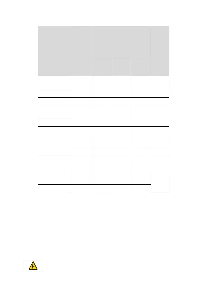
Refer to the preceding table for the model selection for a paralel inverter system.
Note:
Select braking resistors according to the resistance and power data provided by our company.
The braking resistor may increase the braking torque of the inverter. The preceding table
describes the resistance and power for 100% braking torque, 10% braking usage, 50% braking
usage, and 80% braking usage. You can select the braking system based on the actual operation
conditions.
When using an external braking unit, set the brake voltage class of the braking unit properly by
referring to the manual of the dynamic braking unit. If the voltage class is set incorrectly, the
inverter may not run properly.
Do not use braking resistors whose resistance is lower than the specified

Table of Contents

Related product manuals