HD2 Series Inverter Optional Peripheral Accessories
-394-
minimum resistance. inverters do not provide protection against overcurrent
caused by resistors with low resistance.
In scenarios where braking is frequently implemented, that is, the braking
usage is greater than 10%, you need to select a braking resistor with higher
power as required by the operation conditions according to the preceding
table.
External braking units need to be configured for the 660V models and a parallel 660V large-power
inverter system. Select braking resistors according to the specific requirements (such as the braking
torque and braking usage requirements) on site.
⚫
Do not use braking resistors whose resistance is lower than the specified
minimum resistance. The inverter does not provide protection against
overcurrent caused by resistors with low resistance.
In scenarios where braking is frequently implemented, that is, the braking
usage exceeds 10%, you need to select a braking resistor with higher power
as required by the operation conditions according to the preceding table.
D.8.2 Braking resistor cable selection
Braking resistor cables should be shielded cables.
D.8.3 Braking resistor installation
All resistors must be installed in places with good cooling conditions.
The materials near the braking resistor or unit must be non-flammable. The resistor
surface temperature is high. Air flowing from the resistor is of hundreds of degrees
Celsius. Prevent any materials from contacting the resistor.
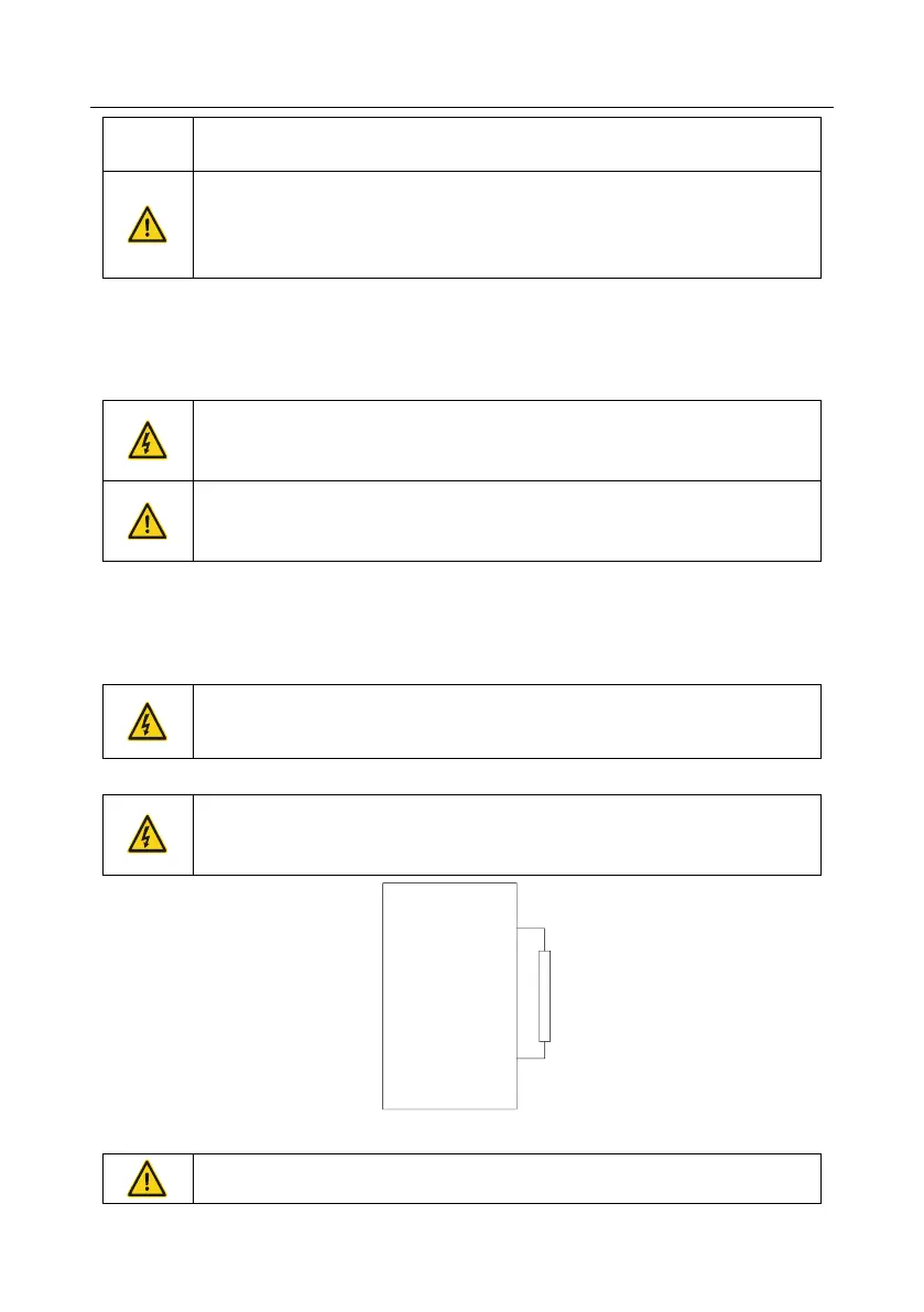
Installation of braking resistors
The 380V 37kW and lower inverter models need only external braking
resistors.
PB and (+) are the terminals for connecting braking resistors.
VFD
PB
External braking resistor
(+)
Installation of braking units
(+) and (-) are the terminals for connecting braking units.
The connection cables between the (+) and (-) terminals of an inverter and