Chapter 5 Relay Ladder Logic Programming 108
-
Filter Function Block (Filter)
iSmart includes 31 independent filter (Filter) command, 5 working mode in each comparator, please see instruction
of comparators and parameters.
Filter Mode 0 (Analog filter)
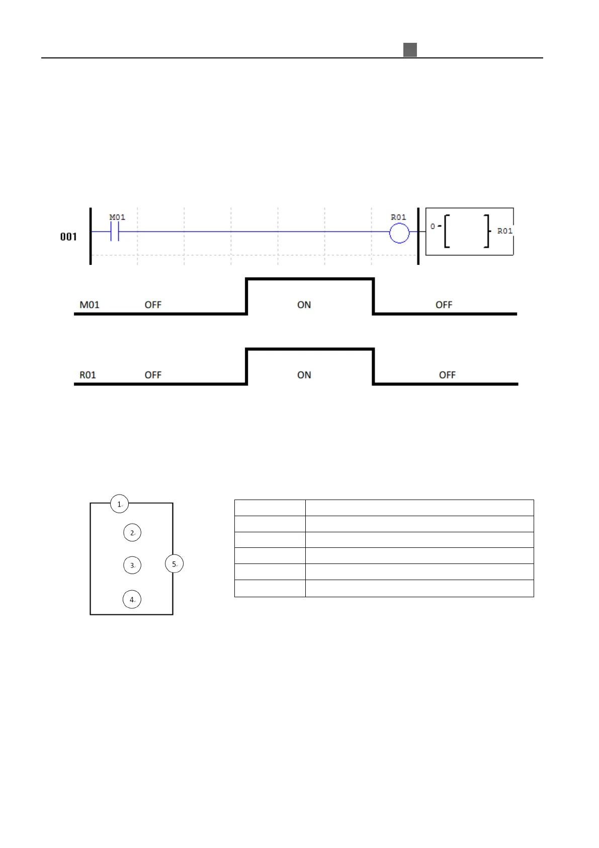
Mode 0 Comparator (Internal Coil) used as internal auxiliary coils. No preset value. In the example below shows
the relationship among the numbered block diagram for a Mode 0 Comparator, the ladder diagram view, and the
software Edit Contact/Coil dialog box.
Filter Mode 1 (Analog filter)
Function instruction
When parameters setup finished, analog filter function will be enabled once enable coil status from 0 to 1. This
will start to do Ax analog value filter according to select sampling mode, the value after filter will be the
current value of F coil.
Software Filter Mode
(Mode 1)
The value will be updated by each scan cycle, it will use last 5 AD average value except maximum and minimum
one.
(Mode 2)
The value will be updated by each 5 scan cycles, it will use 5 time mode 1 value to do average.
(Mode 3)
The value will be updated by each 25 scan cycles, it will use 5 time mode 2 value to do average of maximum
and minimum value.
(
)
 Loading...