Chapter 5 Relay Ladder Logic Programming 109
-
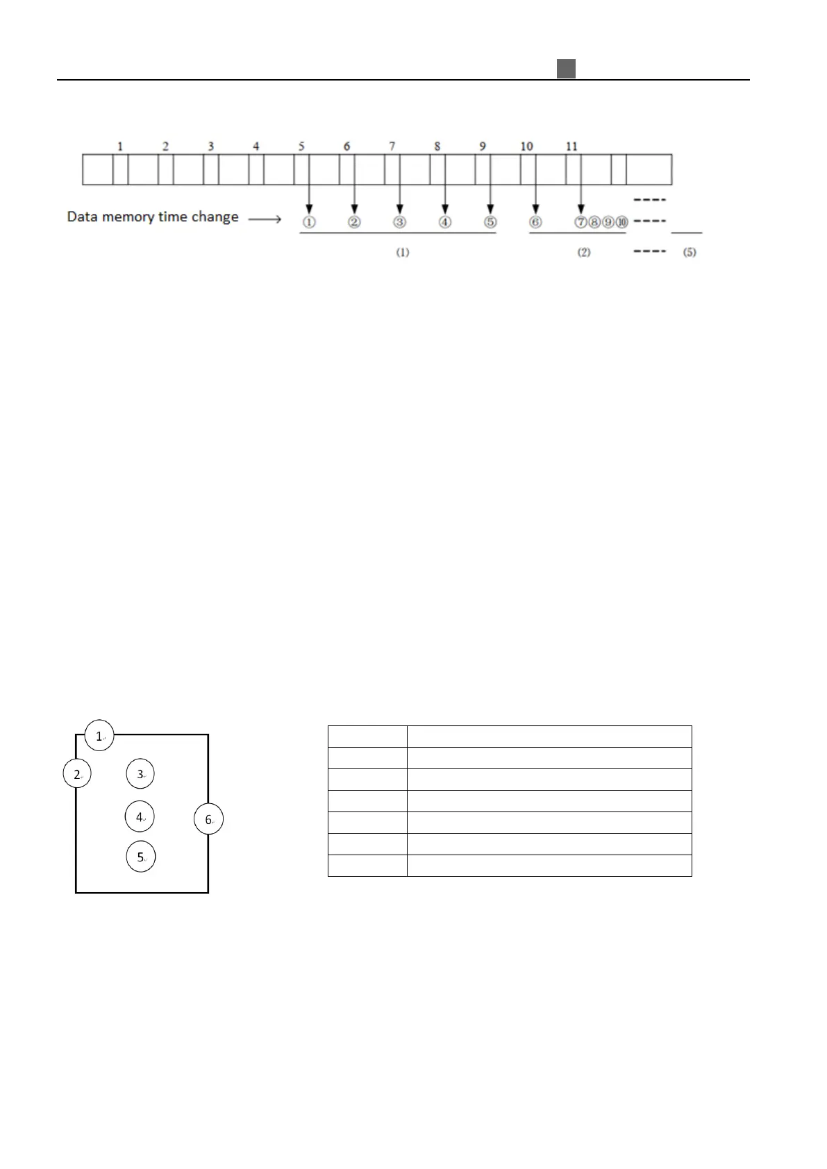
Example : Data 1=161, Data 2=120, Data 3=154, Data 4=160, Data 5=190,Data 6=169,
Data 7=110, Data 8=121, Data 9=150,Data 10=198, Data 11=199。
Mode 1 :
① Updated data=(161+154+160) / 3=158 - filter (1, 2, 3, 4, 5), the maximum value 190
and minimum value 120 will be deleted.
② Updated data=(154+160+169) / 3=161 - filter (2, 3, 4, 5, 6), the maximum value 190
and minimum value 120 will be deleted.
③ Updated data=(154+160+169) / 3=161 - filter(3, 4, 5, 6, 7), the maximum value 190
and minimum value 110 will be deleted.
⑦ Updated data=(121+150+198) / 3=156 - filter(7, 8, 9, 10, 11), the maximum value
199 and minimum value 110
Mode 2 :
It will use 5 time mode 1 value to do average. (①+②+③+④+⑤) / 5
Mode 3 :
It will use 5 time mode 2 value to do average of maximum and minimum value.
(This mode is effective to filter ripple and ripple noise.)
(Maximum value + Minimum value) / 2, the range of these two values is ①②③④⑤.
Filter Mode 2 (Average)
Function instruction
Enable coil ON, average function will start.
This mode is used to calculate analog input average value of time period.
Timing diagram (example)
②
(
)
 Loading...