Chapter 5 Relay Ladder Logic Programming 115
-
※ One controller can use 8 IO Link (L01~L08). Only one IO Link instruction can work at Mode 1(Send mode),
and the other IO Link instructions must be Mode 2 (Receive mode).
The Mode 1: Send the ON/OFF states of the selected coils into the chosen W elements. The available W
elements in the mode 1 depend on the ID setting of that unit, refer to the table in the previous page for more
information.
The Mode 2: Receive the states of the selected W elements and substituting the state of the selected coil. If the select
coil type is input coil I or X, coil status cannot be changed by the state of W elements.
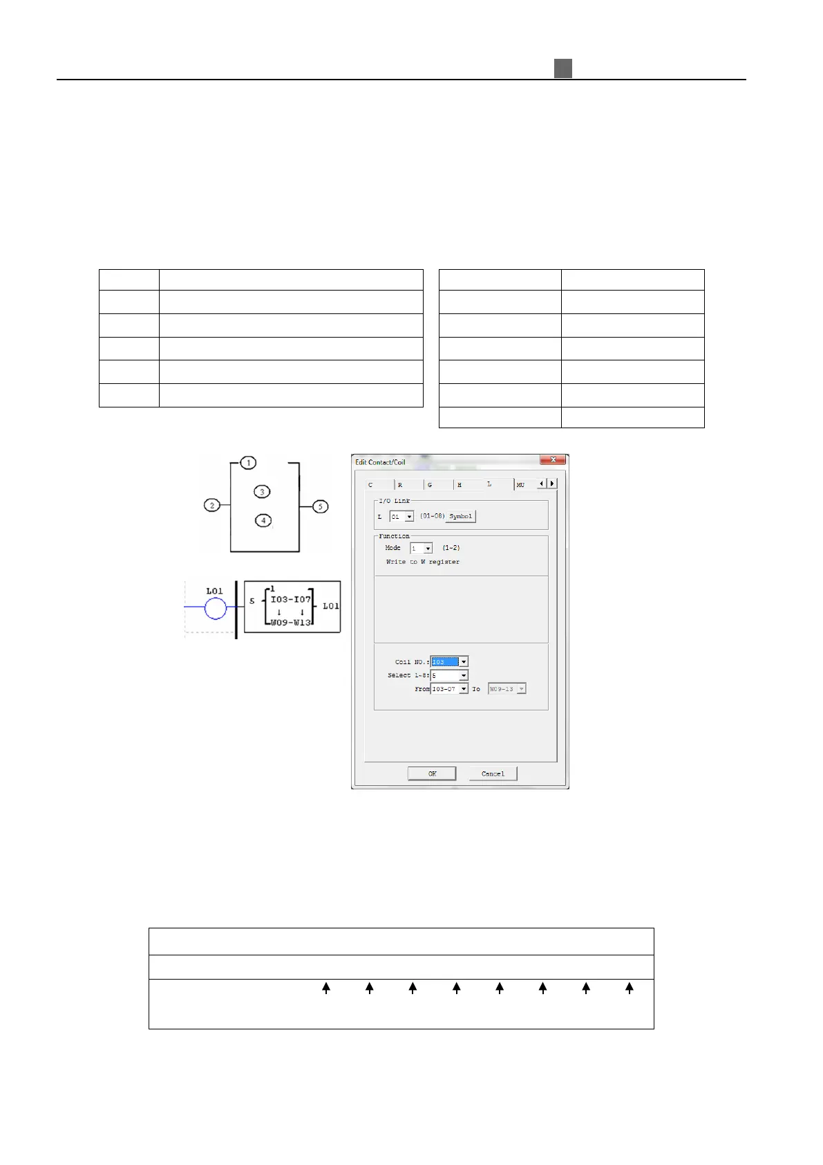
①
Setting mode(1,2) 1:Writing 2:Grading
②
Number of send/receive points (1~8)
③
Chosen coil elements for Write/Grab mode
④
Selected W elements for Write/Grab mode
⑤
I/O link output terminal (L01~L08)
Example 1: IO Link Mode 1
Set ① = 1, ② = 5, ③ = I03~I07 and ID of this unit equal to 01; the state of terminals, I03~I07, will be written
into the corresponding W elements, W09~W13 as shown in below table.
①
②
③
④
Or sending terminal
I03
I04
I05
I06
I07
0
0
0