Chapter 5 Relay Ladder Logic Programming 116
-
Example 2: IO Link Mode 2
Set ① = 2, ② = 5, ③ = M03~M07 and ④ =W17~W21; when enabling the IO Link, the ON/OFF state of
M03~M07 is controlled by the W17~W21.
①
②
③
④
Or sending terminal
M03
M04
M05
M06
M07
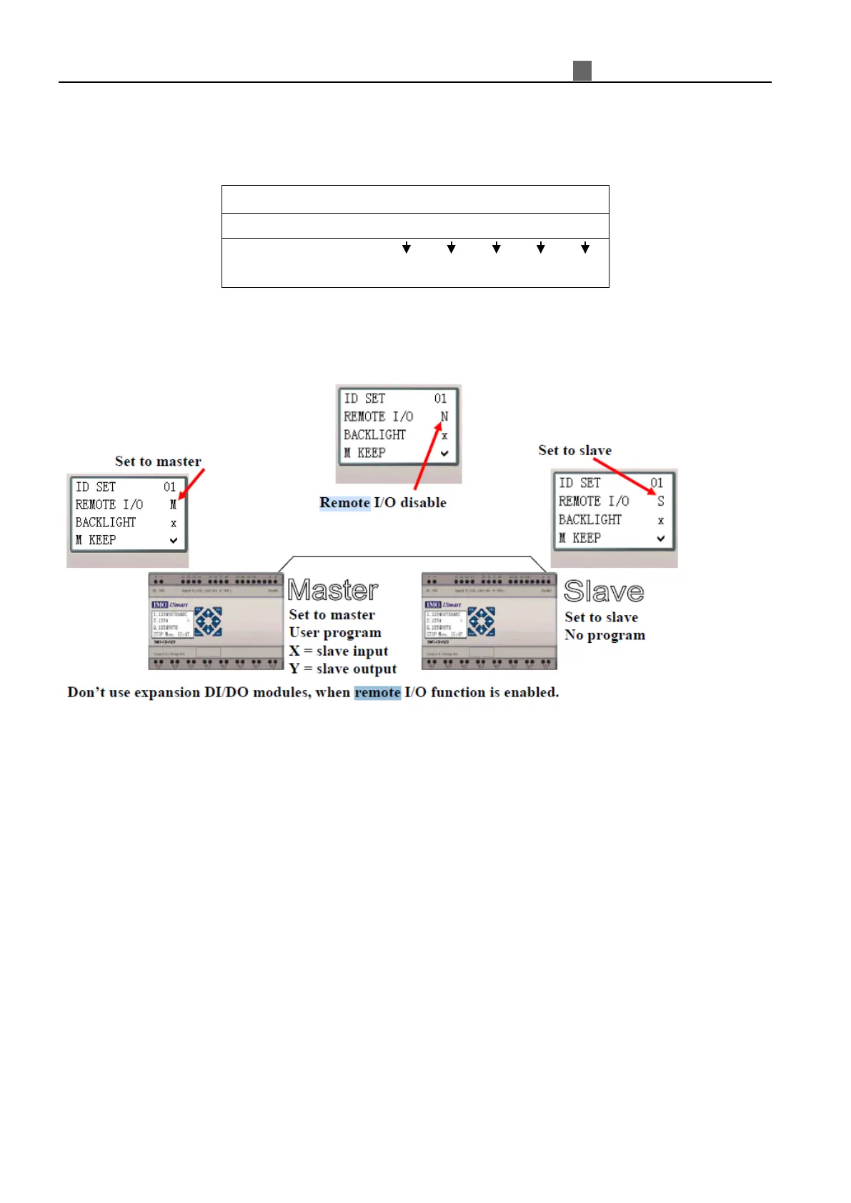
Remote I/O
Remote IO function can make one iSmart as master link to another iSmart as slave; the slave can’t
perform its program. Below figures show how to configure the remote IO system.
Do not use expansion DI/DO modules, when remote I/O function is enabled.
User program not valid
Input = X coil of master
Output = Y coil of master
User program valid
X = slave input