Chapter 6 FBD Block Diagram Programming 144
Mode 4 PLSY Simultaneously Output Mode
PLSY function, output port Q01 and Q02, there are 6 parameters in PLSY mode.
Number of PLSY output pulse (saved in DRC9 register)
:
PLSY output frequency (1~1000Hz)
:
Setting value for number of PLSY output pulse (0~32767)
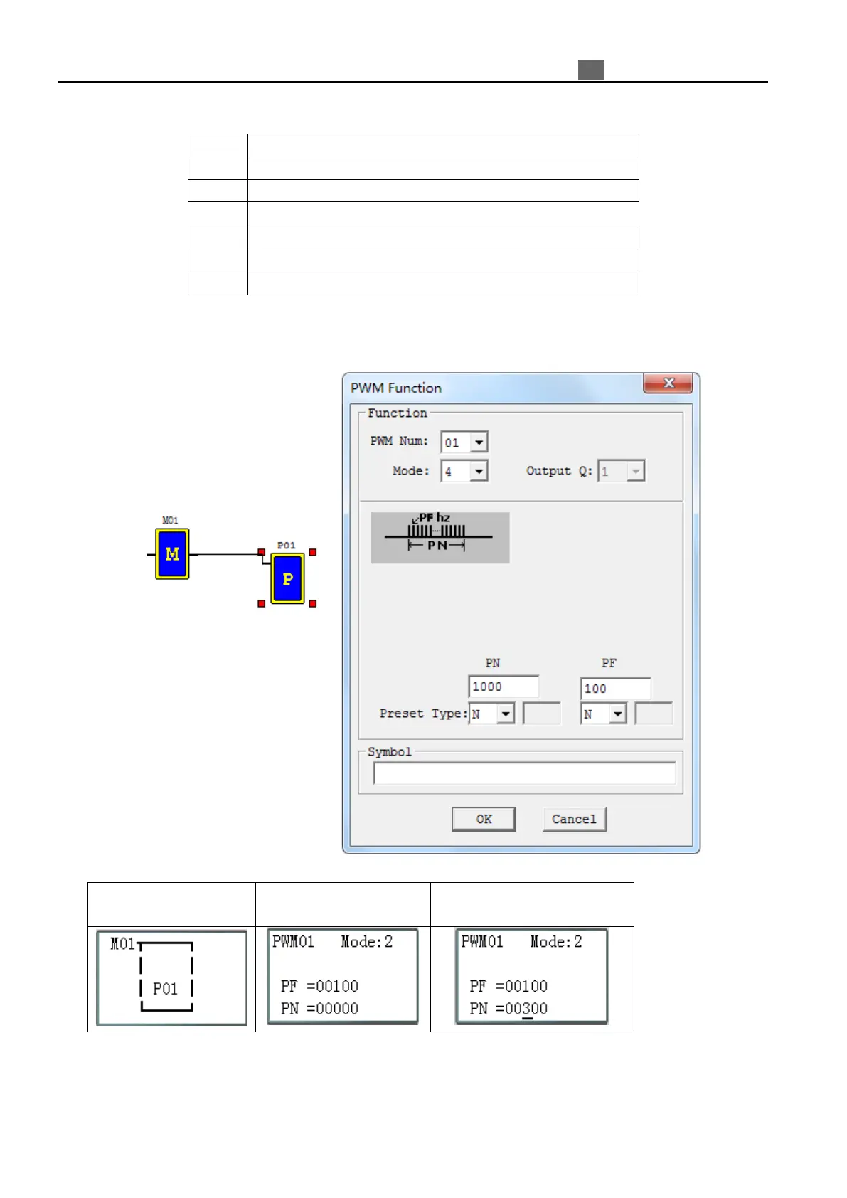
For example:
Coil output display in
FBD mode
Click “OK” to enter
function display
Click “SEL” to select preset
value.
The preset of PLSY output frequency and number of outputs could be a constant, and other encoder code
either. PLSY will stop output once the number of output pulse reaches setting value. If PLSY enabled again, the
setting value of output pulse will be increased from current pulse output number.
※If the setting value of pulse output is 0, PLSY will keep sending output pulse until PLSY disabled.
 Loading...