Intel
®
Server Board S5500BC TPS Connector / Header Locations and Pin-outs
Revision 1.8 Intel order number: E42249-009 93
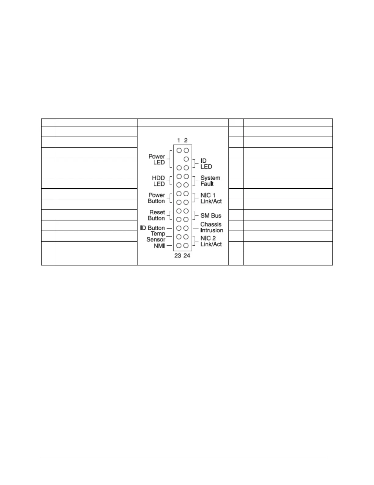
6.5 SSI Front Panel Connector
The Intel
®
Server Board S5500BC provides a 24-pin SSI control panel connector (J9E2) for use
with a non-Intel chassis. Several LEDs, such as the power status LED, HDD LED, and LAN
status LED, are provided on the front panel to provide a visual status. The following table
provides the pin-out information for this connector.
Table 47. Front Panel SSI Standard 24-pin Connector Pin-out (J9E2)
P3V3((HDD Activity LED
Anode)
LED_NIC1_LINK_ACT_BUF_R_N
LED_NIC0_LINK_ACT_BUF_R_N
6.6 I/O Connector Pin-out Definition
6.6.1 VGA Connector
The following table details the pin-out of the VGA connector (J7A1).