EasyManua.ls Logo

Intel SC5650BCDP

Intel SC5650BCDP
162 pages
To Next Page IconTo Next Page
To Previous Page IconTo Previous Page
Loading...
Connector / Header Locations and Pin-outs Intel
®
Server Board S5500BC TPS
Intel order number: E42249-009 Revision 1.8
96
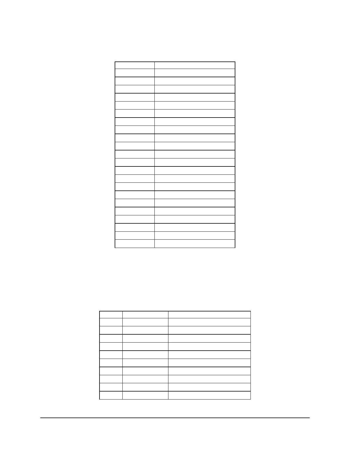
Table 52. External USB and GbE connector Pin-out (J5A1, J6A1)
Pin
Signal Name
1
USB PWR
2
USBP_1N
3
USBP_1P
4
GND
5
USB PWR
6
USB_0N
7
USB_0P
8
GND
9
TERM
10
MDI0P
11
MDI0N
12
MDI1P
13
MDI1N
14
MDI2P
15
MDI2N
16
MDI3P
17
MDI3N
18
GND
19
GRN_C
20
GRN_A
21
GRN_C/YEL_A
22
GRN_A/YEL_C
Four ports are connected to the two 2x5 headers (J1A3, J2A2) on the Intel
®
Server Board
S5500BC. The following table provides the pin-out information for the header. The two headers
are identical.
Table 53. Internal USB Header Pin-out (J1A3, J2A2)
Pin
Signal Name
Description
1
USB PWR
USB Power
2
USB PWR
USB Power
3
USB_5N
USB Port 5 Negative Signal
4
USB_6N
USB Port 6 Negative Signal
5
USB_5P
USB Port 5 Positive Signal
6
USB_6P
USB Port 6 Positive Signal
7
Ground
Ground
8
Ground
Ground
9
Key
N/A
10
NC
No Connection

Table of Contents

Other manuals for Intel SC5650BCDP

Related product manuals