Intel
®
Server Board S5500BC TPS Appendix D: POST Code Diagnostic LED Decoder
Revision 1.8 Intel order number: E42249-009 139
Appendix D: POST Code Diagnostic LED Decoder
The BIOS executes platform configuration processes during the system boot. Each process is
assigned a specific hex POST code number. As each configuration routine is started, the BIOS
displays the POST code on the POST Code Diagnostic LEDs on the back edge of the server
board. The Diagnostic LEDs identify the last POST process to be executed.
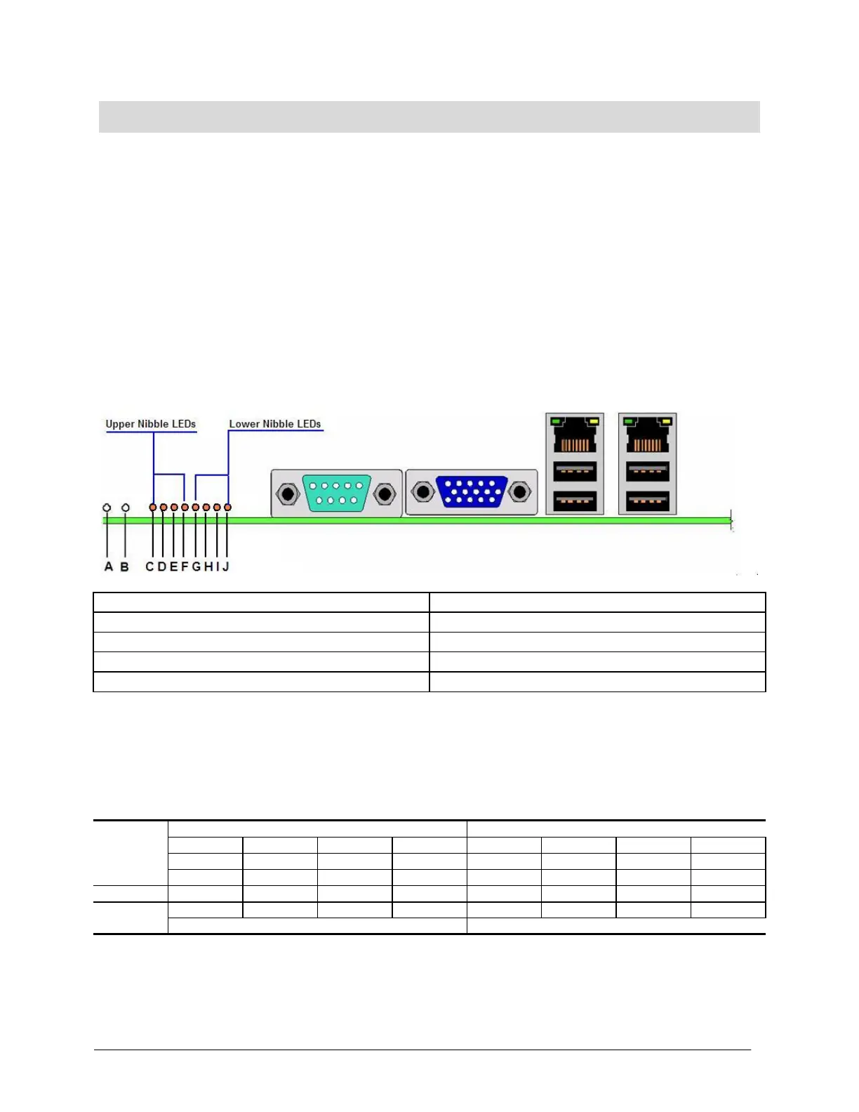
Each POST code is represented by the eight Diagnostic LEDs. The POST codes are divided
into two nibbles, an upper nibble and a lower nibble. The upper nibble bits are represented by
Diagnostic LEDs #4, #5, #6, #7. The lower nibble bits are represented by Diagnostics LEDs #0,
#1, #2 and #3. Given the bit is set in the upper and lower nibbles, and then the corresponding
LED is lit. If the bit is clear, corresponding LED is off.
as
C. Diagnostic LED #7 (MSB LED)
J. Diagnostic LED #0 (LSB LED)
Figure 48. Diagnostic LED Placement Diagram
In the following example, the BIOS sends a value of ACh to the diagnostic LED decoder. The
LEDs are decoded as follows:
Table 80. POST Progress Code LED Example
Upper nibble bits = 1010b = Ah; Lower nibble bits = 1100b = Ch; the two are concatenated as
ACh.