iPECS UCP
Hardware Description and Installation Manual Issue 1.3
108
To install the button kit for the LIP-9048DSS
Prepare your LIP-9048DSS for connection depending on the type of LIP phone. The setting
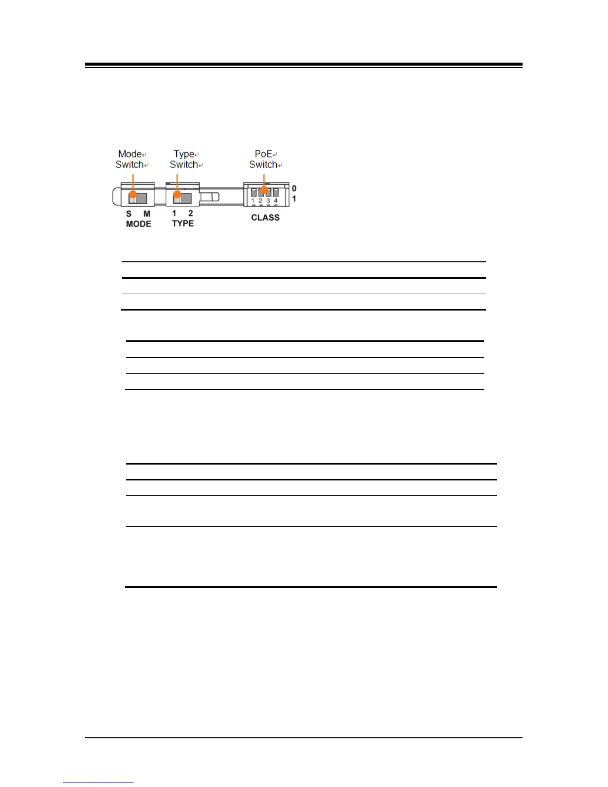
switches are hidden on the back of right side of the LIP-9048 DSS. Before you begin, remove
protective cover from the LIP-9048 DSS.
Power Mode: The MODE switch is used to choose the power mode between Slave and Master.
LIP-9048DSS receives power from another DSS.
LIP-9048DSS provides power itself.
Protocol Type: The TYPE switch is used to choose a call protocol type between iPKTS and SIP.
iPKTS protocol type of communication supported.
SIP protocol type of communication supported.
PoE Class: The PoE (Power over Ethernet) Class is indicated the class of the Powered Device
(PD), and CLASS switch is used to select the PoE class. DSS module supports all 4 classes
listed in below table.
-. One LIP-9048DSS or two LIP-9048DSS
2 0.84W to 6.49W
-. One LIP-9048DSS with a LIP-9020
-. Two LIP-9048DSS with a LIP-9020
3 0.49W to 12.95W
-. One LIP-9048DSS with a LIP-9030
-. Two LIP-9048DSS with a LIP-9030
-. One LIP-9048DSS with a LIP-9040
-. Two LIP-9048DSS with aLIP-9040
The default switch position is '0'.
• '0' means the power OFF status and it does not support PoE power.
• '1' means the power ON status and it does support PoE power.
1 Set the power mode, protocol type, and PoE class in advance as described above.
2 Make sure that the Joint Bracket is aligned with the side of the LIP-9048 DSS, and insert
the one side of the Joint Bracket into the mounting holes.