SECTION 3 - CHASSIS & SCISSOR ARMS
3121166 – JLG Lift – 3-57
Pothole Switch Replacement
(Service Kit - 1001109345)
NOTE: Omit step 1 following if switches are the outboard of
frame rails design.
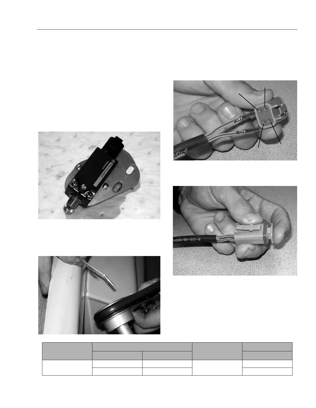
1. Mount the new switches to the new mounting plates
using the supplied screws, nuts and washers.
Tighten switch securely to the mounting plate. Note
there is a right side and left side mounting plate,
the plate mounting holes will mount towards the
center of the machine on both sides.
2. Strip approximately 1/4" of insulation off of the wires
of the existing wire harness. Using a crimping tool
install a new socket terminal onto each of the
stripped ends of the existing wiring harness wires.
3. Remove the wedge lock (orange) from the front end
of the new connector, then load the socket terminals
into the back of the connector.
NOTE: Reference the chart below for proper pin loading.
4. With the socket terminals properly installed, re-insert
the wedge lock (orange) back into the socket to lock
the socket terminals in place.
EXISTING SWITCH NEW SWITCH
TELEMECHANIQUE HONEYWELL TELEMECHANIQUE
IF EXISTING SWITCH IS
WIRED TO PINS:
13 & 14 3 & 4
NEW CONNECTOR SHOULD
BE LO ADED TO PIN S:
1 & 4
21 & 22 1 & 2 2 & 3