SECTION 3 - CHASSIS & SCISSOR ARMS
3-58 – JLG Lift – 3121166
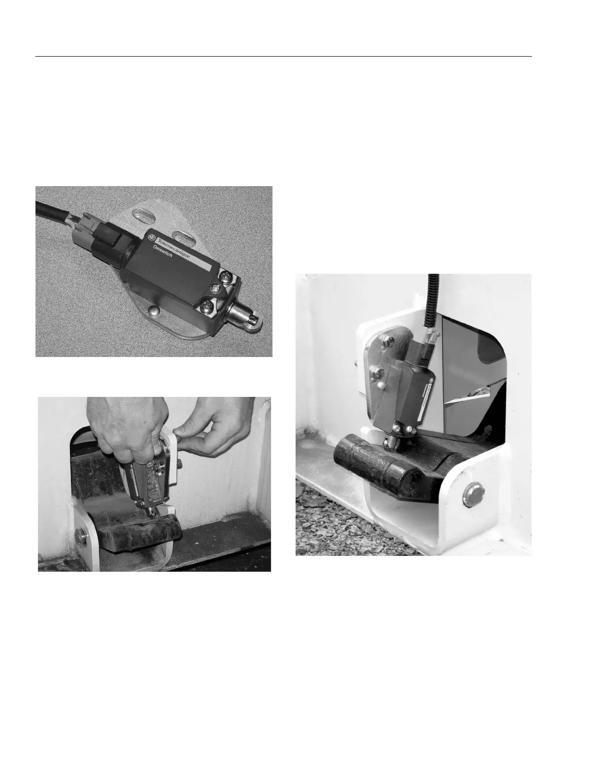
5. Before connecting the wire harness to the new
switch/mount assembly, apply the supplied dielec-
tric grease to both the connector end and the switch
socket pin areas.
NOTE: There is a right side and left side mounting plate, the
plate mounting holes will mount towards the center
of the machine on both sides.
6. Mount the new switch assembly to the machine
using the supplied (10mm) bolts, nuts and washers.
7. Adjust the switch assembly.
SWITCHES INBOARD (SHOWN BELOW)
When pothole bar is in the deployed position, adjust
the switch/bracket assembly down until the plunger
"clicks". Tighten the switch/bracket mounting screws
until secure.
SWITCHES OUTBOARD
When pothole bar is in the deployed position,
depress the plunger fully and release just past the
"click". Tighten the switch mounting screws until
secure.
NOTE: Do not push the switch body down in contact with the
pothole crank link.
8. Repeat this procedure on the opposite side pothole
switch.
9. Power up machine and operate lift and drive to
ensure proper function.