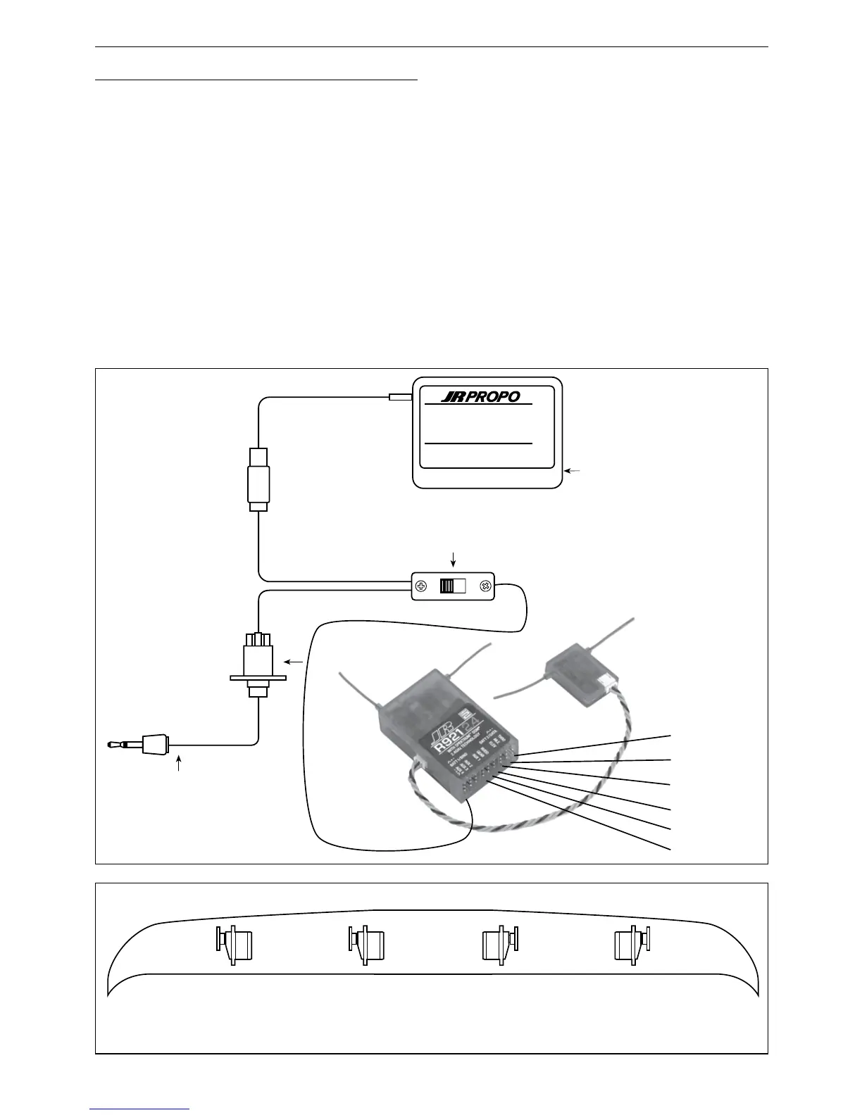
Step #1 Servo Assignment
S-41
Channel Assignment
Important: In glider mode, the channel assignment
(servo lead positions in the receiver) of the X9303
2.4 is different than previous JR radios. This new
channel assignment has two important advantages:
• It allows a 6-channel receiver to be used to
control the 6 functions commonly found on
full-function Sailplanes.
• It locates commonly mixed channels, like right
and left ailerons, right and left flaps, rudder and
elevator for (V-tail), next to each other in the data
stream minimizing synchronizing delay issues.
Install the servos in the correct location in the receiver per
the chart and illustration below.
Servo Channel # Receiver Position
Left Aileron 1 Throttle
Right Aileron 2 Aileron
Elevator 3 Elevator
Rudder 4 Rudder
Right Flap 5 Gear
Left Flap 6 Flap/ Aux. 1

 Loading...