MULTI-POINT MIXER – Example: ELIMINATE PITCH-COUPLING
A-43
The example below demonstrates a Multi-Point Program
Mix for aircraft that pitch towards the landing gear when
holding Rudder for knife-edge flight – commonly known
as Pitch-Coupling. If a mix is set up to provide an
appropriate amount of up Elevator for different amounts of
Rudder input, the aircraft will fly straight without pitching
to the landing gear while holding Rudder during knife-
edge flight.
This Multi-Point mixer uses the Rudder as the Master and
the Elevator as the Slave. The mix is turned on and off
with the GEAR switch.
The Mix parameters will be selected and set in the
following order: Program Mix number, Master, Slave,
Switch, Set Points Travel/Direction, and Offset. This is
generally a good sequence to follow when setting up
Multi-Point Programmable Mixers.
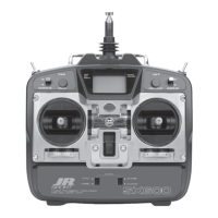
1. Program Mix Number. Highlight and select one
of the Multi-Point Programmable Mixers (PROG.
MIX1 or PROG.MIX2) to obtain the first Multi-Point
Programmable Mix display. Then press ACT next to
CLR or highlight and select INH to obtain the main
mix display. The example is using PROG.MIX1.
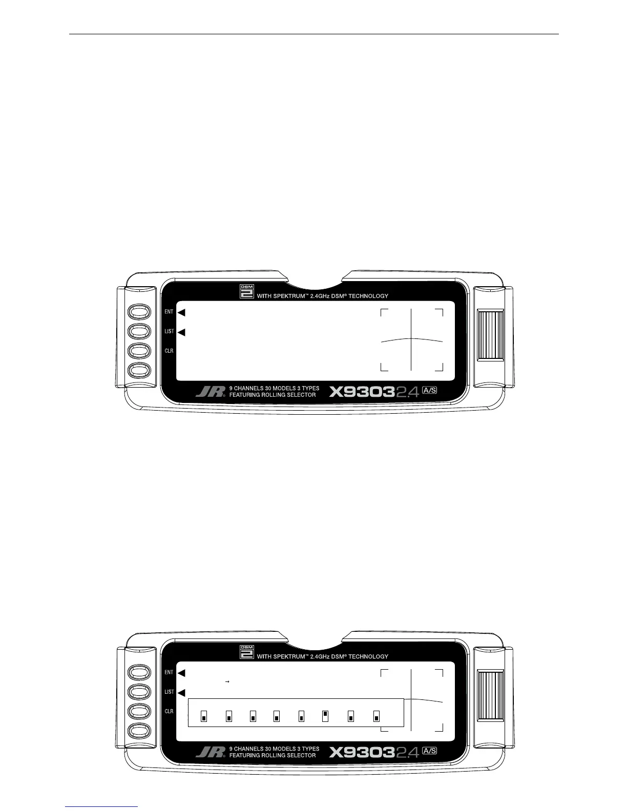
2. Select Master. All Programmable Mixers default
to Throttle as both the Master and the Slave
(THROTHRO). The first THRO is the Master and
the 2nd THRO represents the Slave.
Highlight and select the first THRO to the left of the
arrow to obtain a list of channels and select RUDD
as the Master.
3. Select Slave. Highlight and select THRO to the
right of the arrow to obtain a list of channels that
can be used as the Slave. Highlight and select ELEV
as the Slave.
4. Select Switch. Scroll over to and select SW
SELECT to obtain a list of switches and then highlight
and select GER as the switch to be used to turn the
mixer on and off. The GER indicator should now be in
the upper or ON position at the bottom of the display.
Any of the switches can be used and multiple switches
can be used if so desired. The example is using only
the Gear switch.

 Loading...