Step #14 Spoiler to Elevator Curve Mix (Programmable Mix 1)
S-49
On most sailplanes, deploying flaps causes the aircraft
to pitch up. This pitching is non-linear and typically the
airplane pitches up dramatically the first 25% of flap
travel but becomes less dramatic during the 25% through
50% range, and very little additional up pitching occurs
from 75 to 100% flaps. The X9303 2.4 incorporates a
preprogrammed curve mix that mixes the spoiler stick
(landing flaps) to the elevator.
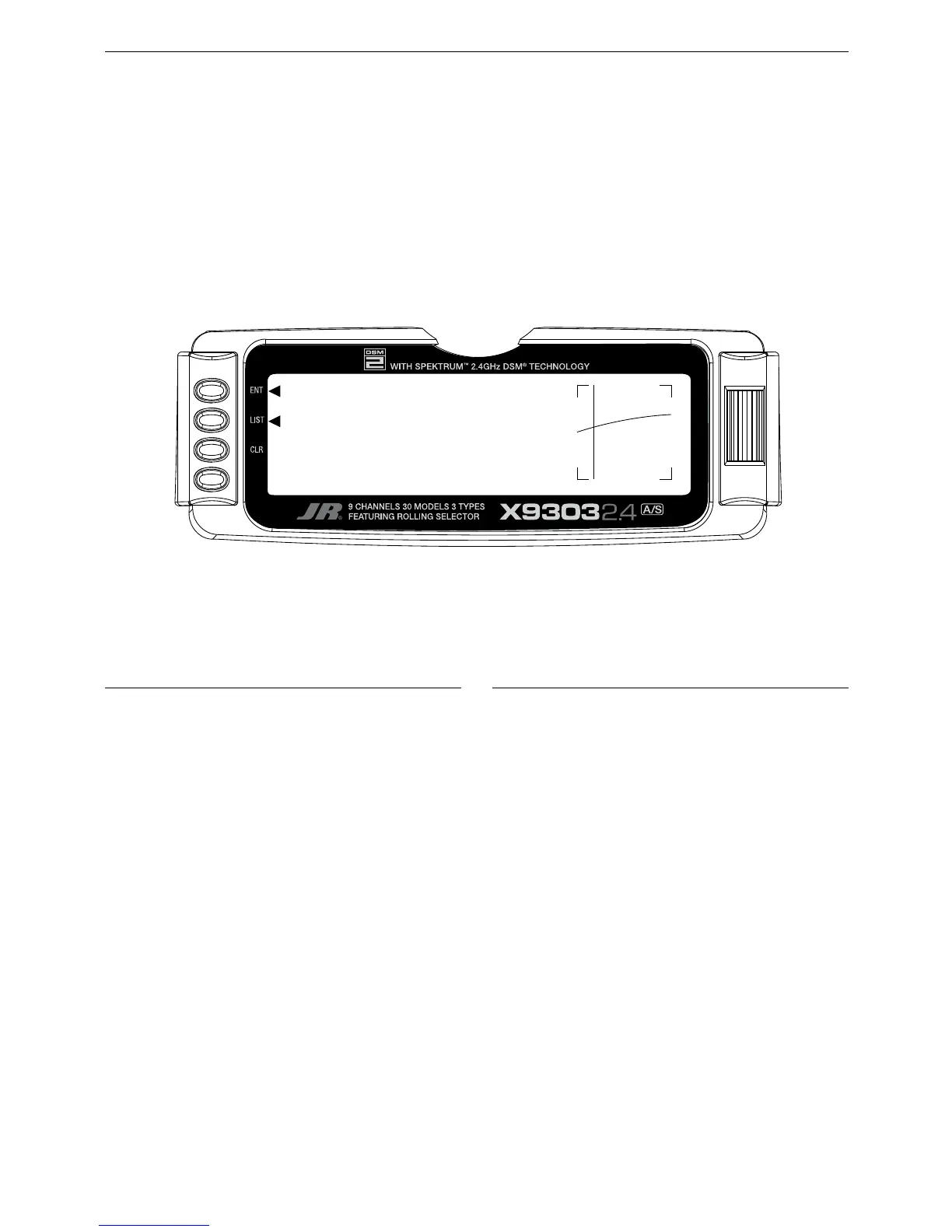
In FUNC.LIST rotate the Selector until PROG Mix1
is highlighted. Press the Selector to access the
Programmable mix 1 spoiler-to-elevator curve mix. Rotate
the Selector to highlight the desired point then press the
Selector to access the point’s value. Rotate the Selector
to change the value. All points on the curve can be
adjusted using this method. The below curve shows the
typical values that are needed for a common performance
sailplane. Press the LIST button to return to the Function
Mode screen.
Setting-up Flight Modes
Up to this point we have established the foundational
programming that will be common to all flight modes.
Now we will focus on the specifics of setting up each
individual flight mode.
We will be individually programming the following
parameters for each of the selected flight modes
(Launch, Cruise, Land).
• Dual and Exponential rates for Aileron, Elevator
and Rudder
• Setting preset positions for the Camber, Flaperon
and Elevator
• Elevator-to-Flap Mixes
• Aileron-to-Flap Mixes
• Aileron Differential
• Flight Mode Delay
• Camber Adjustment
• Aileron-to-Rudder Mixes
• Spoiler-to-Elevator Curve Mix (elevator
compensation)
Launch Mode Setup
In Step #8, Establishing Flight Modes, flight modes were
programmed to operate from the left front 3-position
switch. To select Launch mode, the left 3-position
switch must be moved in the up position. In the main
(info) screen LAUNCH will appear in the upper portion
of the display when Launch mode is selected. When
making programming changes/adjustments in Launch
mode, this 3-position switch must remain in the upper
position during the process to allow the results of those
adjustments to be seen on the model.

 Loading...