NOTE: To maintain proper airflow through the services gateway, leave blank
faceplates in place over slots that do not contain GPIMs. Do not remove a
blank faceplate unless you are immediately installing a GPIM in the empty
slot. For more information about removing a blank faceplate, see “Removing
a Blank Gigabit-Backplane Physical Interface Module Faceplate from the
SRX Series Services Gateway” on page 255.
NOTE: Installing a GPIM on the SRX550 Services Gateway is similar to
installing a GPIM on the SRX650 Services Gateway.
To install a GPIM:
1. Attach an electrostatic discharge (ESD) grounding strap to your bare wrist, and connect
the strap to one of the ESD points on the chassis. For more information about ESD,
see “Preventing Electrostatic Discharge Damage to the SRX Series Services Gateway”
on page 246.
2. Grasp the handles on each side of the GPIM faceplate, and align the edges of the
GPIM circuit board with the guide rails at each side of the GPIM slot.
NOTE: If you are installing a double-high, double-wide GPIM such as the
24-Port Ethernet XPIM, you must remove the center GPIM slot bracket.
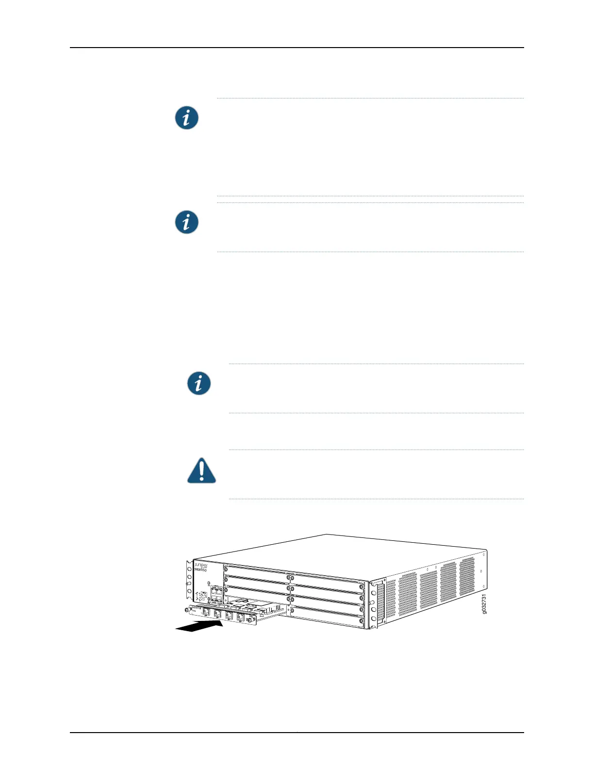
3. Slide the GPIM into the services gateway until it seats firmly in the device. See
Figure 44 on page 257 for information.
CAUTION: Slide the GPIM straight into the slot to avoid damaging the
components on the GPIM.
Figure 44: Installing a Single-High, Single-Wide GPIM in an SRX650
Services Gateway
4. Using a Phillips (+) screwdriver, tighten the captive screws on each side of the GPIM
faceplate.
257Copyright © 2015, Juniper Networks, Inc.
Chapter 30: Replacing Gigabit-Backplane Physical Interface Modules