120 Keysight N9927-90001 User’s Guide
Time Domain – Option 010
Gating
Gating Shape
This setting defines the filter characteristics of the gate function. Choose from
Minimum, Normal, Wide, Maximum.
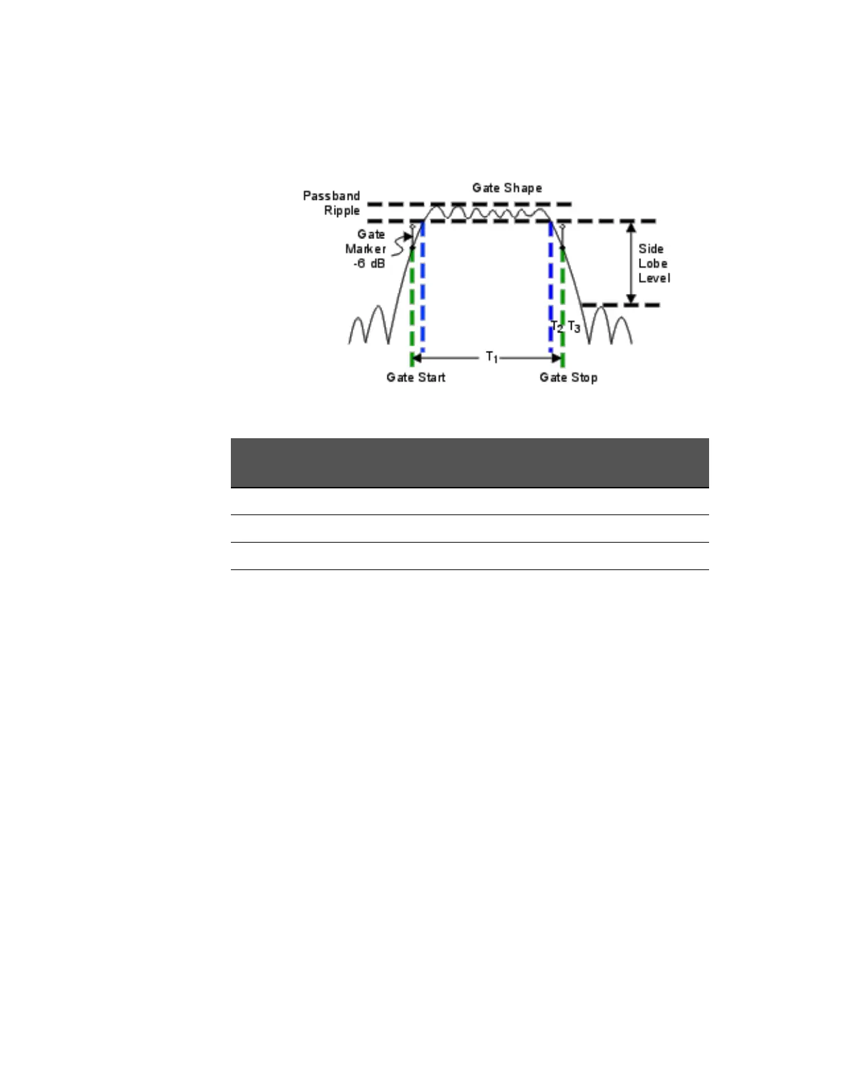
Time domain Gate Shape setting is shown in the graphic above.
Cutoff time is the time between the stop time (-6 dB on the filter skirt) and the
peak of the first sidelobe.
—T
1
is the gate span, which is equal to the stop time minus the start time.
—T
2
is the time between the edge of the passband and the 6 dB point,
representing the cutoff rate of the filter.
—T
3
is the time between the 6 dB point and the edge of the gate stopband.
For all filter shapes T2 is equal to T3, and the filter is the same on both sides of
the center time.
Minimum gate span is twice the cutoff time. Each gate shape has a minimum
recommended gate span for proper operation. This is a consequence of the
finite cutoff rate of the gate. If you specify a gate span that is smaller than the
minimum span, the response will show the following effects:
— distorted gate shape that has no passband
—distorted shape
— incorrect indications of start and stop times
— may have increased sidelobe levels.
Gate Shape Passband
Ripple
Sidelobe
Levels
Cutoff Time Minimum Gate
Span
Minimum ±0.1 dB -48 dB 1.4/Freq Span 2.8/Freq Span
Normal ±0.1 dB -68 dB 2.8/Freq Span 5.6/Freq Span
Wide ±0.1 dB -57 dB 4.4/Freq Span 8.8/Freq Span
Maximum ±0.01 dB -70 dB 12.7/Freq Span 25.4/Freq Span
 Loading...


