3 IQ Analyzer (Basic) Mode
3.1 Complex Spectrum Measurement
2 For USB connection, you can connect at any time before starting the Signal Analyzer
software
3 Make sure latest version of M8131A SFP is installed on Signal Analyzer (available at
Keysight.com)
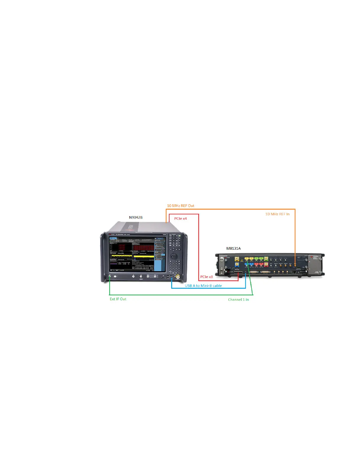
4 Connect the input signal to the Input connector of your instrument:
–
For N9041B, input signal must be connected to RF Input 2 as shown below
–
For N9042B, connect to RF In, however if V3050A is connected, use the connector from
V3050A
5 Connect the Ext IF Out connector on the instrument to the Channel 1 input of the Digitizer:
–
For N9041B, this is located on the rear upper left of the instrument
–
For N9042B, this is located on the lower left of the front panel
6 For best frequency accuracy, connect the 10MHz reference out of the instrument to the
10MHz reference in of the oscilloscope
IF Path Auto
When IF Path Auto is ON, the measurement automatically selects between the IF
Paths based on the current measurement’s Digital IF Bandwidth setting. When the
measurement tries to set a Digital IF Bandwidth between 10 and 25 MHz, the IF Path
parameter automatically switches from 10MHz to 25MHz . When the
measurement sets the Digital IF Bandwidth back to a value narrower than 10 MHz,
then the IF Path automatically switches from 25MHz to 10MHz . This is the same
for the other paths as well. If the instrument has options B25 and B1X installed but
not B40, when the IF Path Auto is set ON and the current measurement sets the IF
Bandwidth from 14MHz to 26MHz, the IF Path automatically switches from 25MHz
to 140MHz since the 40MHz path is not available.
247 IQ Analyzer Mode User's &Programmer's Reference