3 IQ Analyzer (Basic) Mode
3.1 Complex Spectrum Measurement
–
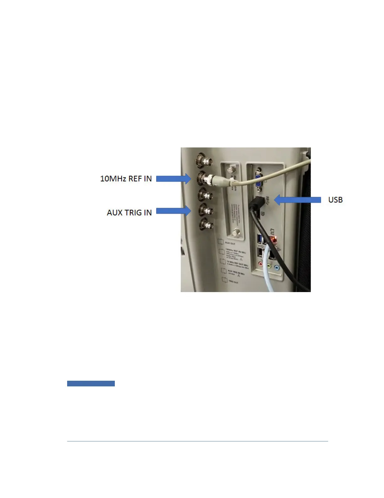
The IF signal is digitized with the oscilloscope and routed back to the instrument
via the USB3 cable. You must connect this cable to one of the two USB3 Type A
connectors on the instrument’s rear panel. There are other USB ports on the
front and rear panel of some instruments, but Keysight recommends the use of
the USB3 ports on the rear panel, because those are high speed ports. Only
these ports have the SS symbol
–
The USB port of the DSOS804A oscilloscope is located on the side panel, as
shown below:
Connecting an M8131A as an External Digitizer
The M8131A Digitizer is a 2-slot module that plugs into a Keysight AXIe chassis
(M9502A or M9505A). In order to connect the Digitizer, the instrument must
connect to the PCIe or USB3 port of the AXIe chassis. USB3 connection is slower,
but easier to use, and is the only option for N9041B.
To connect an M8131A for External Digitizer Control (EDC):
1 Establish PCIe or USB connection between AXIe chassis and Signal Analyzer
IMPORTANT
When using a PCIe connection, it is critical that the instrument and the AXIe
chassis are both powered down
before
making the connection. Once
connected, power up
only
the AXIe chassis and wait for the LED at the
bottom right front to turn green.
Then
, power up the instrument. Failure to
follow this power-up sequence may result in system instability. Turning off
the AXIe chassis or unplugging the PCIe cable while the instrument is
running may result in system instability
IQ Analyzer Mode User's &Programmer's Reference 246