3 IQ Analyzer (Basic) Mode
3.2 IQ Waveform Measurement
–
For N9042B, this is located on the lower left of the front panel
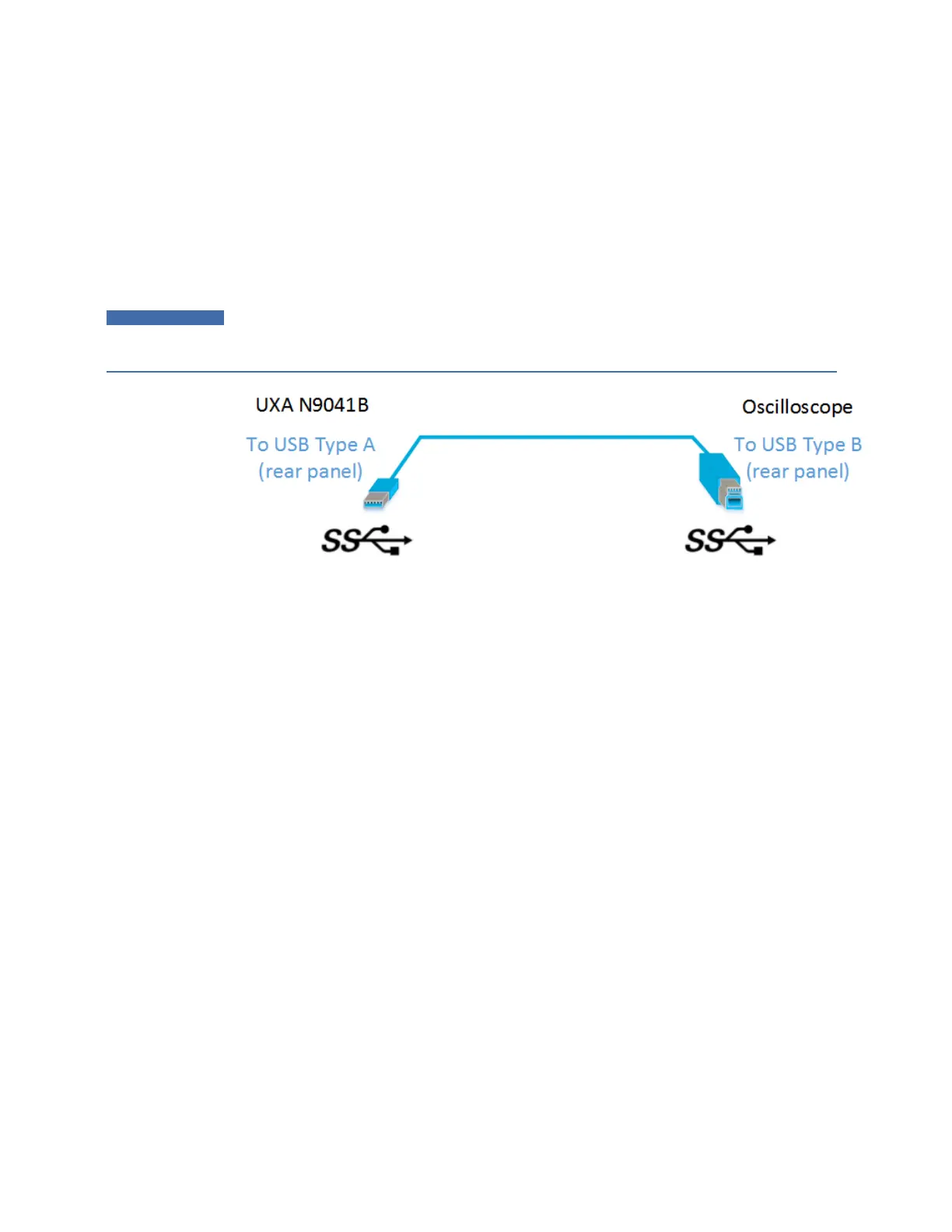
3 Connect a USB3 cable (blue connectors) from the rear panel of the instrument to the rear
panel of the Oscilloscope
4 For best frequency accuracy, connect the 10MHz reference out of the instrument to the
10MHz reference in of the oscilloscope
IMPORTANT
Make sure to use a USB3 cable (with blue connectors);
not
an older USB2 cable.
Connect it as shown below:
Use only connectors with the SS symbol as shown above.
When a valid USB3 connection is established, the instrument displays the message
“Updating Hardware Configuration”. When this connection is to a supported
oscilloscope, the instrument displays the message “External Oscilloscope
connected.” Once this connection is established, the External selection in the IF
Path menu will be selectable.
If, after the External IF Path selection is shown in the menu, the USB3 cable to the
oscilloscope is disconnected, the External IF Path selection will still appear but will
be disabled (grayed-out). If you press the grayed-out External selection, the error
message “Oscilloscope not connected” is displayed. If you send the SCPI command
to select External while External is grayed-out, error “-224: Illegal parameter value;
Oscilloscope not connected” is generated.
Once a valid scope connection is made, "Apply EDC Preset" on page 384 becomes
available (otherwise, it is grayed-out) and the EDC Preset information appears
below the Apply EDC Preset button, as in the example below:
IQ Analyzer Mode User's &Programmer's Reference 378