K2600R Disassembly/Assembly
Opening the K2600R
3-3
Removing the Audio Board
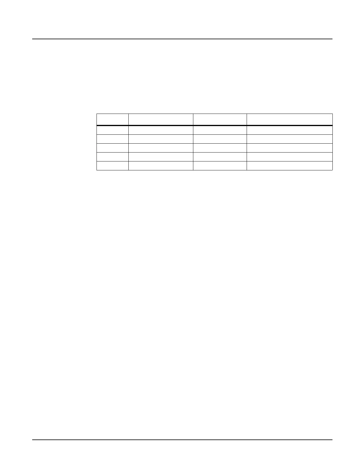
1. Disconnect the cables listed in Table 3-1.
All flat ribbon cables use cable locking clips that secure the cables to the connectors.
Remove the cable locking clip from the flat ribbon cable on the Audio Board. Be sure to set
it safely aside so that you can reinstall it when you reconnect the cable.
2. Remove the three screws that secure the Audio Board to the rear panel.
3. Remove the Audio Board.
Replacing the Audio Board
1. Place the Audio Board in position so that the output jacks are aligned properly with the
openings provided for them in the rear panel.
2. Install the three screws that secure the Audio Board to the rear panel.
3. Connect the flat ribbon cable to location J601 and install the locking cable clip.
4. Connect the remaining cables listed in Table 3-1.
Removing the Digital I/O Option Board
You must remove the Audio Board before removing the Digital I/O Option Board. Follow the
procedure on page 3-3 to remove the Audio Board.
1. Remove the cap from the Optical Out jack.
2. Remove the two Digital I/O port screws.
3. Remove the four Digital I/O Out and In jack screws.
4. The Digital I/O Option Board is mounted component side down. Move the board slightly
toward the front panel to free the jacks from the openings provided for them in the rear
panel.
5. Disconnect the three cables listed in Table 3-2.
Ref. Name Cable Type Destination
J601 DAC flat ribbon CPU Board
J602 Audio Power stranded Power Supply Board
J611 Sampler shielded wire Sampling Board
J612 Volume shielded wire Phone/Volume Board
J615 Phones shielded wire Phone/Volume Board
Table 3-1 K2600R Audio Board cables
 Loading...