K2600R Disassembly/Assembly
Opening the K2600R
3-9
11. If the K2600R you are servicing has a Digital I/O Option, follow the procedure on
page 3-4 to replace it. If the K2600R you are servicing has a Small Digital I/O Board,
follow the procedure on page 3-5 to replace it.
12. Follow the procedure on page 3-3 to replace the Audio Board.
Removing the Power Supply Board
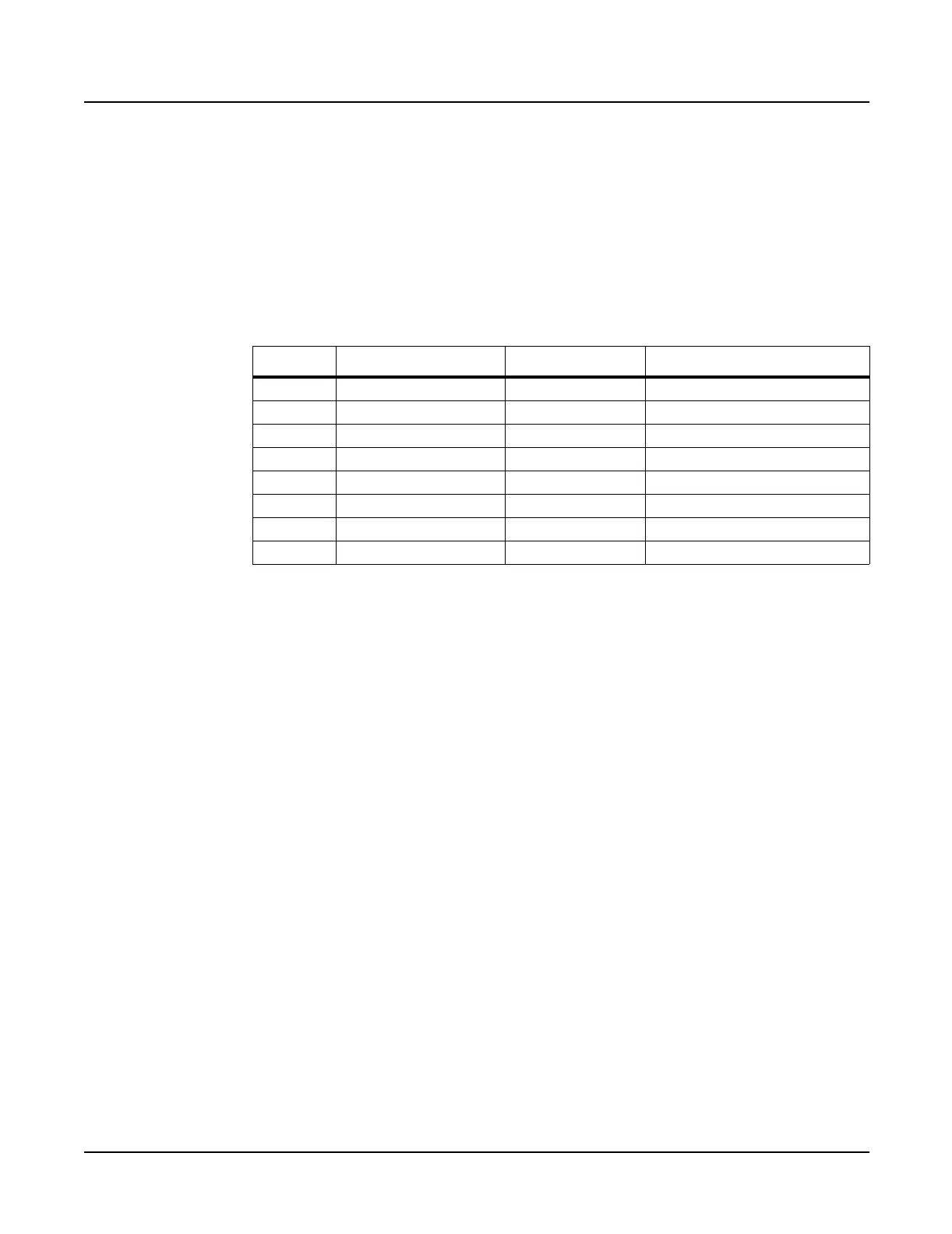
1. Disconnect the cables listed in Table 3-5.
2. The Power Supply Board is secured to the K2600R bottom enclosure with four screws.
Two screws are located at the left edge of the board (as viewed standing at the rear panel),
and two screws are located at the heatsink mounting bracket. Remove these screws.
3. Remove the Power Supply Board.
Replacing the Power Supply Board
1. Place the Power Supply Board in position over the mounting standoffs on the bottom
enclosure. Be certain that the area is clear of disconnected cables and loose hardware.
2. Install the four screws that secure the Power Supply Board to the bottom enclosure.
3. Connect the cables listed in Table 3-5.
Removing the Transformer
1. Disconnect the stranded wire cable from the transformer to the AC Entry Module.
2. Disconnect the two stranded wire cables from the Power Supply Board at locations J101
and J102.
3. Disconnect the stranded wire cable from the Backlight Board. This cable connects to J104
on the Power Supply Board.
4. Remove the four screws and split washers that secure the transformer to the bottom
enclosure, and remove the transformer.
Ref. Name Cable Type Destination
J101 System Secondary stranded wire Transformer
J102 HDD Secondary stranded wire Transformer
J103 Fan Supply stranded wire Fan Assembly
J104 Backlight Supply stranded wire Backlight Power Board
J105 CPU DC Power stranded wire CPU Board
J106 HDD Supply stranded wire HDD
J107 Audio Power stranded wire Audio Board
J108 Scanner Power stranded wire Front Panel/Scanner Board
Table 3-5 Power Supply Board cables
 Loading...