3-18
K2600R Disassembly/Assembly
Front Panel Assembly
2. Connect the flat ribbon and shielded wire cable to the floppy disk drive. Be sure to install
the cable locking clip on the flat ribbon cable.
3. Standing at the front panel, tilt the front end of the disk drive mounting bracket down
toward you and lower it into position.
4. Install the four screws that secure the disk drive mounting bracket to the bottom
enclosure.
5. Connect the stranded wire cable from the LCD Board to the Backlight Board.
6. Connect the shielded wire cable from the Power Supply Board to the Front Panel/Scanner
Board.
7. Connect the flat ribbon cable from the CPU Board to the Front Panel/Scanner Board, and
install the locking cable clip.
8. Reapply the tape over the two cables that secure them to the top of the disk drive
mounting bracket.
Removing the Hard Disk Drive
1. Remove the cable locking clip and disconnect the flat ribbon cable from the Hard Disk
Drive.
2. Disconnect the power cable from the Hard Disk Drive. This cable connects to J106 on the
Power Supply Board.
3. Remove the four screws that secure the drive to the mounting bracket.
4. Remove the Hard Disk Drive.
Replacing the Hard Disk Drive
1. Position the Hard Disk Drive into the mounting bracket.
2. Install the four screws that secure it to the mounting bracket.
3. Connect the power cable from the Power Supply Board to the Hard Disk Drive.
4. Connect the flat ribbon cable from the CPU Board to the Hard Disk Drive. Be sure to
install the cable locking clip.
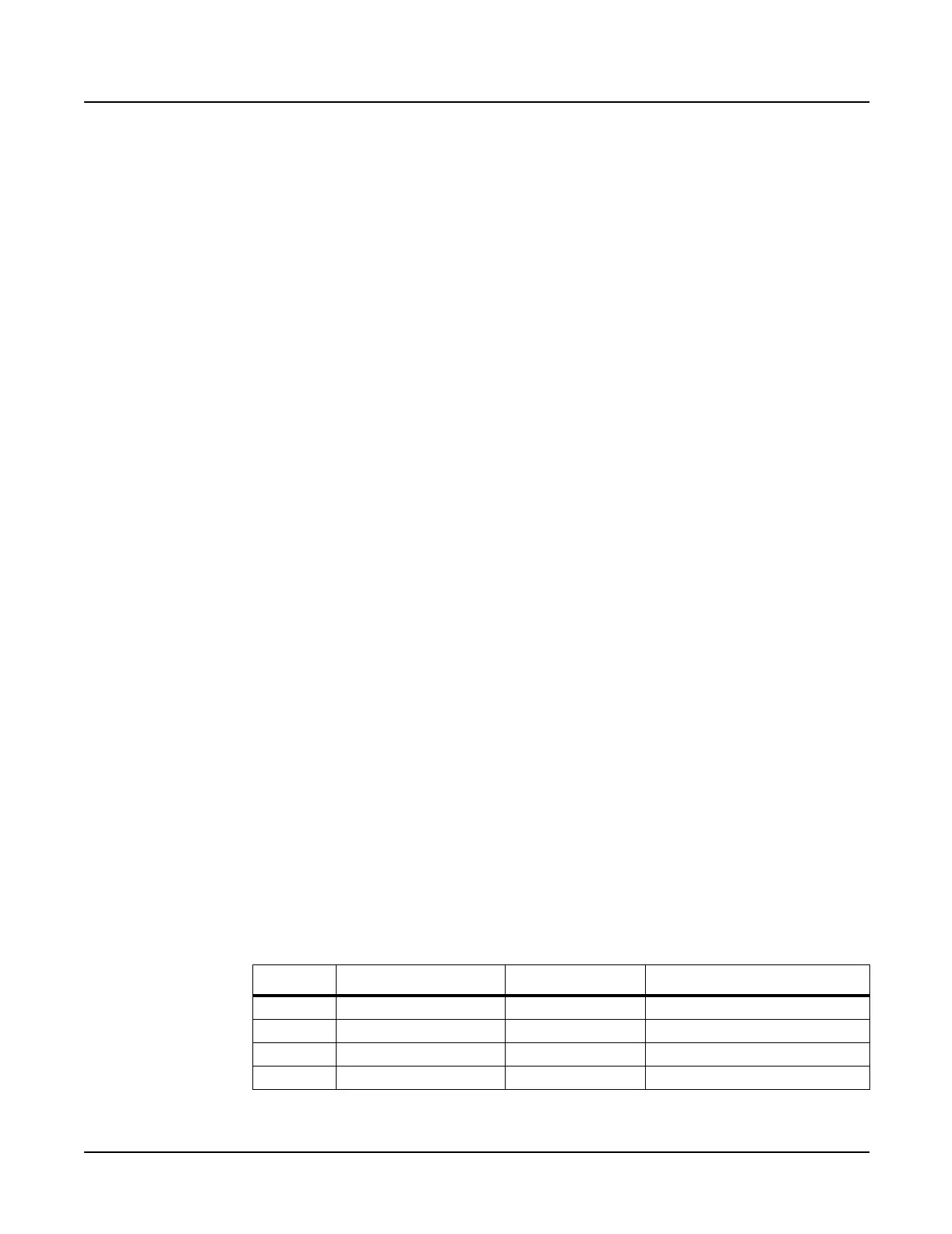
Removing the Sampling Board
1. Disconnect the cables listed in Table 3-6.
Ref. Name Cable Type Destination
J1101 CPU Host flat ribbon CPU Board
J1102 SMP DIG I/O shielded wire Digital I/O Board
J1103 Audio shielded wire Audio Board
J1108 Optical Digital Out shielded wire Digital I/O Board
Table 3-6 Sampling Board cables
 Loading...