4-8
K2600/K2600X Disassembly/Assembly
Top Enclosure
Removing the Digital I/O Option Board
1. Following Steps 2 and 3 disconnect the cables listed in Table 4-2.
2. Remove the cable locking clip and disconnect the flat ribbon cable. Be sure to place the
cable locking clip safely aside so that you can install it when replacing the board.
3. Disconnect the shielded wire cables.
4. Remove the cap from the Optical Out jack.
5. The Digital I/O Option Board is secured to the rear panel with six screws. Remove these
screws, and remove the Digital I/O Option Board.
Replacing the Digital I/O Option Board
1. Position the board so the Digital I/O jacks, Optical jack, and Digital I/O ports are aligned
properly through the openings provided for them in the rear panel.
2. Install the four screws that secure the Digital I/O Out and In jacks to the rear panel.
3. Install the two screws that secure the Digital I/O ports to the rear panel.
4. Install the cap on the Optical jack.
5. Connect the cables listed in Table 4-2. Be sure to install the cable locking clip on the flat
ribbon cable.
Removing the Small Digital I/O Board
1. Remove the four screws that secure the Digital I/O Out and In jacks to the rear panel.
2. Remove the cap at the Optical Out jack.
3. Disconnect the two cables listed in Table 4-3.
4. Remove the Small Digital I/O Board.
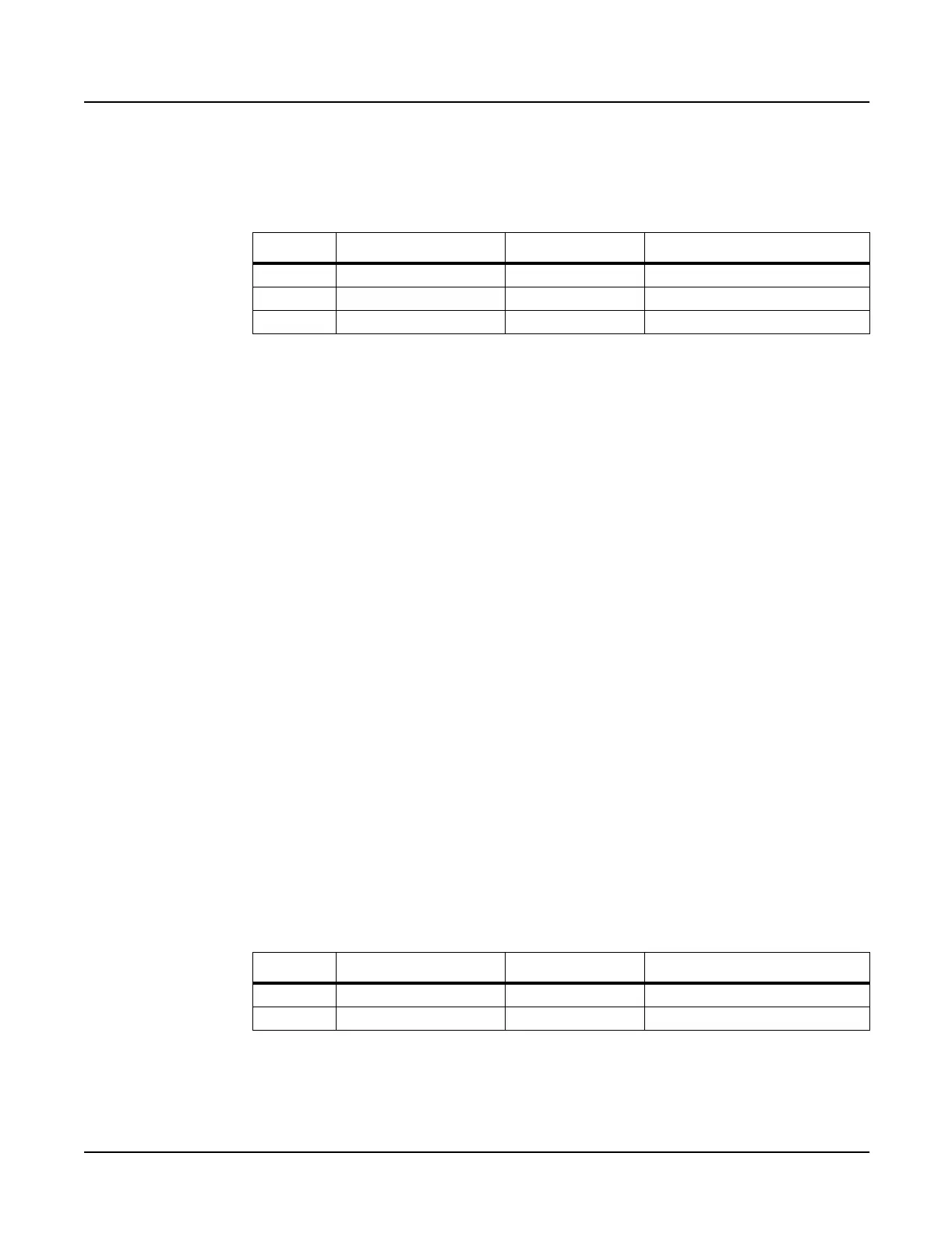
Ref. Name Cable Type Destination
J1001 Digital I/O to DSP flat ribbon DSP Board
J1002 Sampling Bd. (SOB) shielded wire Sampling Board
J1003 Sampling Bd. (SOB) shielded wire Sampling Board
Table 4-2 K2600/K2600X Digital I/O Option Board cables
Ref. Name Cable Type Destination
J1002 Sampling Bd. (SOB) shielded wire Sampling Board
J1003 Sampling Bd. (SOB) shielded wire Sampling Board
Table 4-3 K2600 Small Digital I/O Board cables
 Loading...