K2600/K2600X Disassembly/Assembly
Top Enclosure
4-13
Removing the Control Panel Board
1. Follow the procedures on page 4-11 to remove the LCD and Backlight Boards. If the unit
you are servicing has a Sampling Board, follow the procedure on page 4-9 to remove it.
2. The Control Panel-to-Keyboard Scanner Board flat ribbon cable is soldered into the
Control Panel Board. Remove the cable locking clip and disconnect the flat ribbon cable
from the Keyboard Scanner Board, location J705.
3. The enclosure support wall secures the front edge of the Control Panel Board to the top
enclosure. Remove the enclosure support wall screws, and set the wall aside.
Note: If you are servicing a K2600, there are seven screws securing the enclosure support
wall. If you are servicing a K2600X, there are eight screws.
4. Once the enclosure support wall is removed, you will notice that the Control Panel Board
also has adhesive-backed black felt that secures the front edge of the board to the top
enclosure. Peel back the black felt to release the front edge of the board.
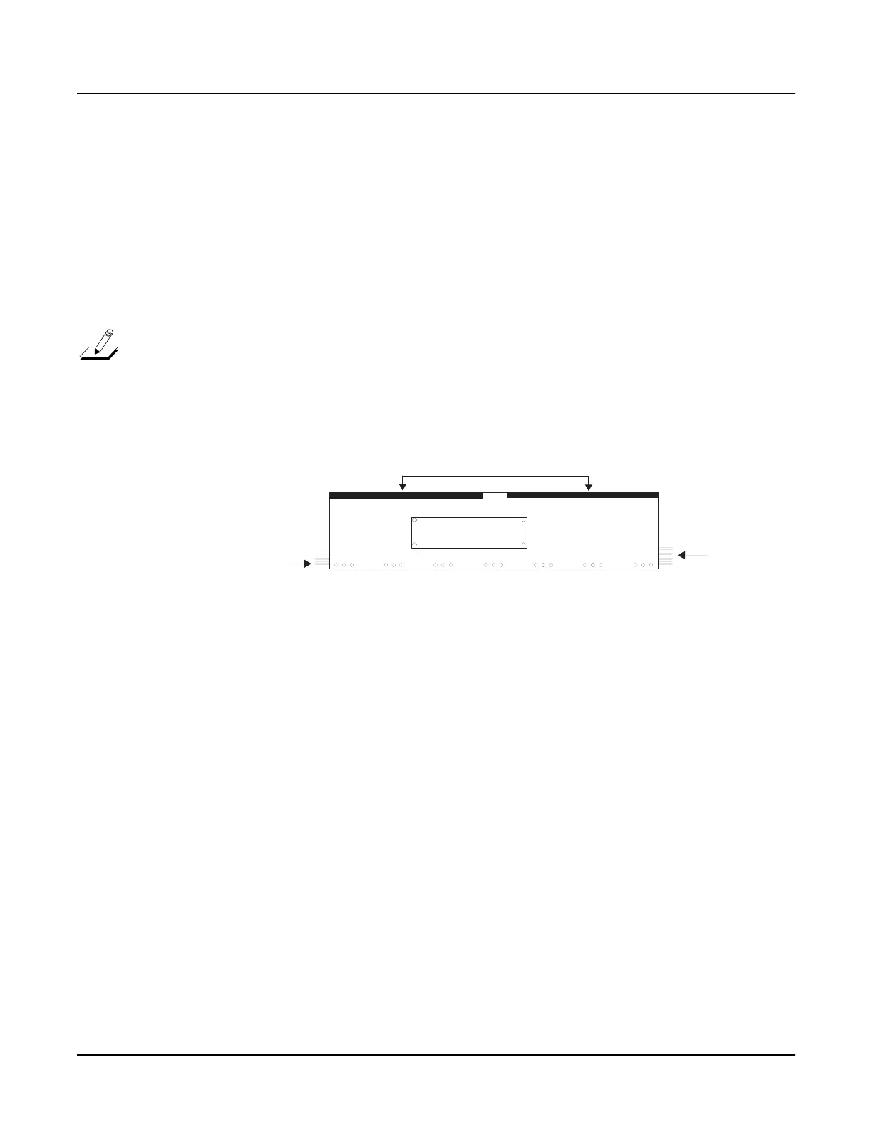
Figure 4-7 Control Panel Board
5. Remove the seven screws that secure the rear panel edge of the Control Panel Board to the
top enclosure.
6. Slightly lift the Control Panel Board up horizontally just enough to insure that the
spinknob and switch caps clear the openings provided for them.
7. Lift the right side of the board up vertically to gain access to the flat ribbon cable that
connects the Control Panel Board to the Slider Board.
8. This cable is soldered into the Control Panel Board. Disconnect the cable from the Slider
Board, location J303.
9. Remove the Control Panel Board.
Replacing the Control Panel Board
1. Position the Control Panel Board over the top enclosure and lower the left side of the
board so that you can connect the flat ribbon cable to the Slider Board.
2. Once this cable is connected, lay the Control Panel Board flat, then raise the top enclosure
up slightly to verify that the spinknob and switch caps are correctly positioned through
the openings provided for them in the top enclosure.
3. Install the seven screws that secure the Control Panel Board to the top enclosure.
4. Reapply the adhesive-backed black felt on the front edge of the board.
LCD Board
Ribbon cable to
Slider Board
Ribbon cable to
Scanner Board
Black felt
 Loading...