3-6
K2600R Disassembly/Assembly
Opening the K2600R
7. To release the DSP Board from the standoffs on the left side of the board, squeeze the top
of the standoffs and slightly lift the left side of the DSP Board.
8. Once the DSP Board is free of the standoffs, lift the DSP Board straight up to disconnect
the two 50-pin connectors from the CPU Board.
Replacing the DSP Board
1. Place the DSP Board in position onto the four nylon PC board standoffs.
2. Verify that the DSP Board pins are lined up properly with the two 50-pin connectors
located on the CPU Board.
3. Press the DSP Board down to insert the pins on the back of the DSP Board into the two
50-pin connectors on the CPU Board. This will also secure the DSP Board into the four
standoffs.
4. Connect the flat ribbon cable from the CPU Board to the Sampling Board.
5. Connect the flat ribbon cable from the LCD Board to the CPU Board.
6. Be sure to replace the locking cable clips on the flat ribbon cables.
7. If the K2600R you are servicing has a Digital I/O Option, follow the procedure on
page 3-4 to replace it. If the K2600R you are servicing has a Small Digital I/O Board,
follow the procedure on page 3-5 to replace it.
8. Follow the procedure on page 3-3 to replace the Audio Board.
Removing the CPU Board
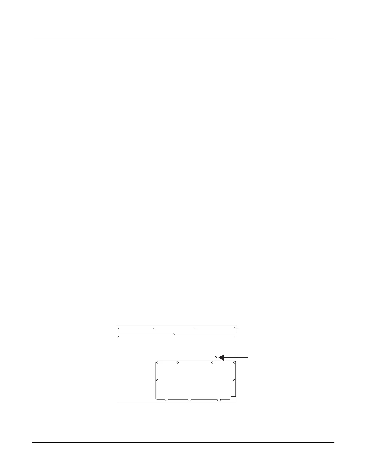
The CPU Board is secured at several locations. There are five attachment points on the bottom
enclosure. The first is a moveable holding bracket secured with a screw, see Figure 3-2. The other
four locations are mounting posts that rise up out of the bottom enclosure. Three nylon PC
board standoffs and a screw secure the CPU Board to the four mounting posts, see Figure 3-3.
The CPU Board is also held in place by the fasteners that secure the SCSI ports and MIDI jacks to
the rear panel.
Figure 3-2 K2600R bottom
Front panel
Rear panel
Holding
bracket
screw
Access panel
 Loading...