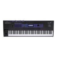
K2600R Disassembly/Assembly
Opening the K2600R
3-7
1. Follow the procedures previously described to remove the Audio Board, Digital I/O
Option (if installed) or the Small Digital I/O Board, and the DSP Board.
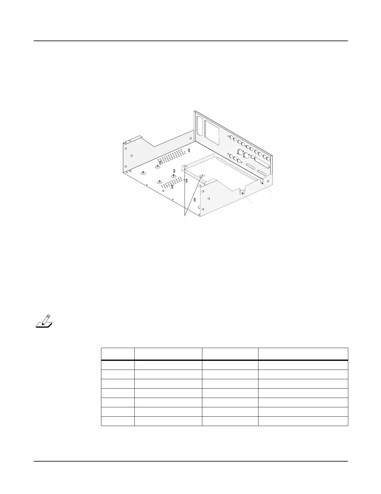
2. Place the K2600R on its side. Hold the CPU holding bracket and remove the holding
bracket screw from the bottom enclosure. Place the CPU holding bracket aside.
Figure 3-3 K2600R internal attachment points
3. Place the K2600R flat in its normal position.
4. All flat ribbon cables use cable locking clips that secure the cables to the connectors.
Remove the cable locking clips from the flat ribbon cables on the CPU Board. Be sure to set
them safely aside so that you can reinstall them when you reconnect the cables.
5. Disconnect the cables listed in Table 3-4. All but one of these cables connect to the CPU
Board. The exception is Ref. J108, which connects to the Power Supply Board.
Note: The flat ribbon cable that connects the LCD Board to the CPU Board should already
be removed from location J804 on the CPU Board. Therefore, it is not listed in Table 3-4.
Ref. Name Cable Type Destination
J801 Sampler flat ribbon Sampling Board
J805 Floppy flat ribbon Disk Drive
J807 Floppy Power stranded wire Disk Drive
J808 DAC flat ribbon Audio Board
J813 Scanner flat ribbon Front Panel/Scanner Board
J814 DC Power stranded wire Power Supply Board
J108 Scanner Power stranded wire Front Panel/Scanner Board
Table 3-4 Cables to disconnect for CPU Board removal
standoffs
standoff
screw
 Loading...