Power Core User ManualVersion: 6.6.0/3228/539
14. Control Surface Configuration
14.7.5 Fader Mappings
Any fader strip can be mapped to a different control surface position using fader mappings. The system works
by giving every fader strip a unique mapping ID. This includes faders on Layer 1 and Layer 2 for all Fader
Modules.
MF Keys, defined by the configuration, can then reassign any fader ID to any control surface position. For
example, a fader can be cloned by assigning the same ID to two positions. Move one of the cloned faders, and
the other follows; select a new source for the fader, and the other follows.
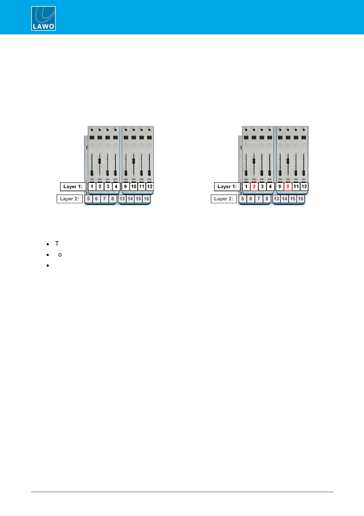
The mapping numbers identify both layers. Therefore Module 1 contains Faders 1 to 4 and 5 to 8; Module 2
starts at Fader 9 and so on.
There are three main applications for fader mappings:
·
To clone a fader - as shown above.
·
To move fader strips – for example, to rearrange the layout for different types of production.
·
To map invisible fader strips onto physical faders – to create additional "layers".
The first two applications are particularly useful for multi-operator layouts, as faders can be cloned at different
operator stations, or the control surface can be re-configured from single to multi-user.