5.2011.8583.0 C
Description 4-3
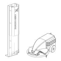
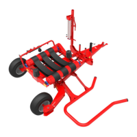
Figure 24. Mixer and feed door
KEY: 1. Mixer knife - 2. Mixer - 3. Counter knife - 4. Feed door
The Mixing and Feeding Robot has the following motors:
• Feed door motor.
• Drive motor left wheel.
• Drive motor right wheel.
• Actuator to lift the skirt.
• Actuator to insert the counter knife inside the mixing bin.
• Mixer motor.
• Dosing roll motor.
The Mixing and Feeding Robot has the following sensors:
• Two inductive sensors at the bottom between the wheels to detect (and follow) metal strips on the
floor.
• Ultrasonic sensors to detect the distance to the feed fence or wall.
• Laser measurement to detect the feed height.
• Gyroscope on the PCB to detect the direction of motion.
• Reed contacts to detect the position of the safety bumper (when the bumper hits an objects the
bumper is pushed out of its original location).
• Proximity switch (position sensor) to detect the dosing roll standby position.
• Voltage detection to detect the voltage on the charger.
• Three load cells to determine the weight in the mixing bin.
• Encoders on the driving motors to determine the travelled distance and calculate the speed.
• Encoder on the door motor to detect the position of the feed door.
• Encoder on the actuator to lift the skirt to detect the position of the skirt.
• Encoder on the actuator to insert the counter knife to detect the position of the counter knife.
in n o vato rs in agriculture