Table18.DIMMinstallationsequence(normalmode)
NumberofDIMMsInstallationsequence(connectors)
Microprocessor1installed
A1,C1,B1,D1,A2,C2,B2,D2
Microprocessor1and2installed
A1,E1,C1,G1,B1,F1,D1,H1,A2,E2,C2,G2,B2,
F2,D2,H2
Table19.DIMMinstallationsequence(sparingmode)
NumberofDIMMsInstallationsequence(connectors)
Microprocessor1installed
A1,A2,C1,C2,B1,B2,D1,D2
Microprocessor1and2installed
A1,A2,E1,E2,C1,C2,G1,G2,B1,B2,F1,F2,D1,
D2,H1,H2
Table20.DIMMinstallationsequence(mirrormode/lockstepmode)
NumberofDIMMsInstallationsequence(connectors)
Microprocessor1installed
A1,B1,C1,D1,A2,B2,C2,D2
Microprocessor1and2installed
A1,B1,E1,F1,C1,D1,G1,H1,A2,B2,E2,F2,C2,
D2,G2,H2
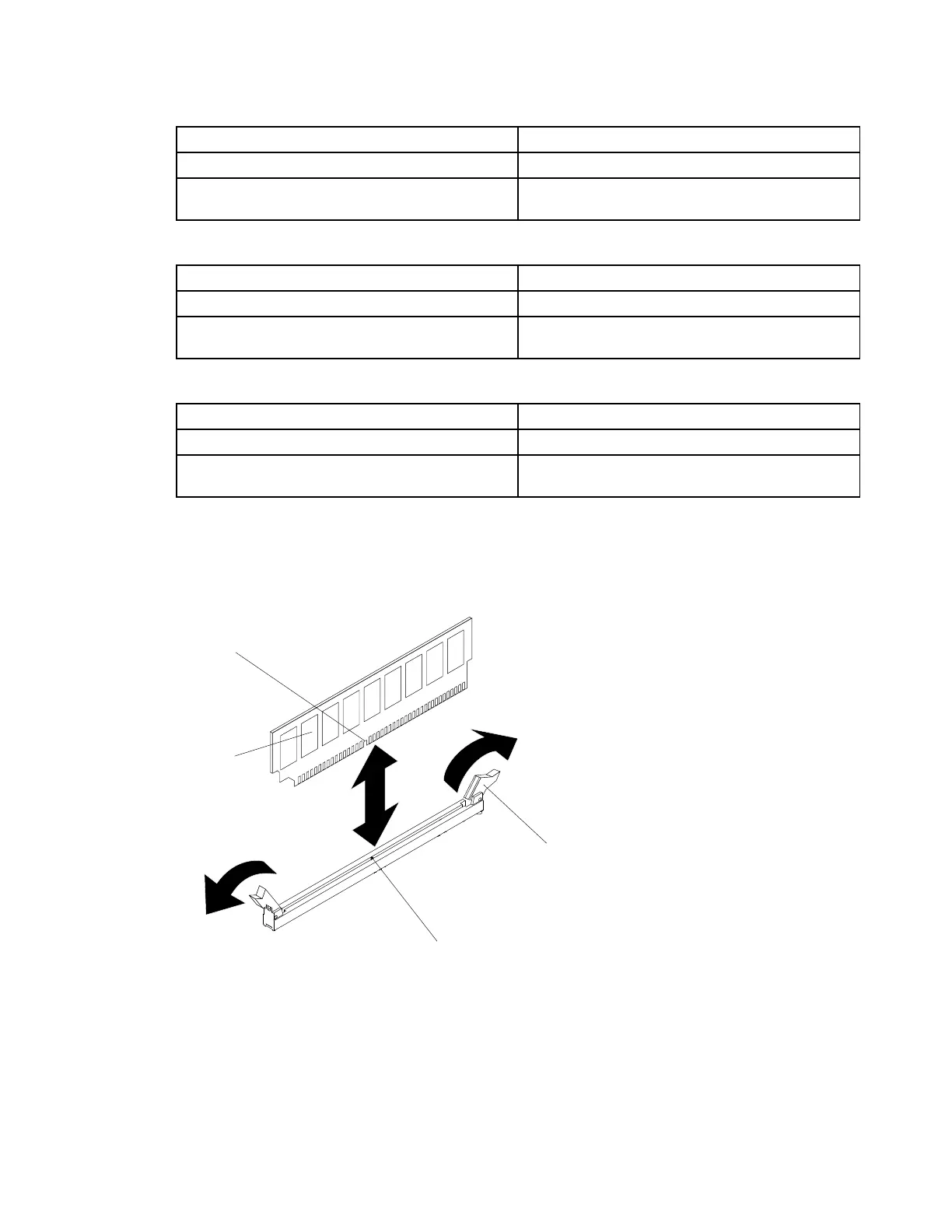
Step4.OpentheretainingcliponeachendoftheDIMMconnector.
Attention:ToavoidbreakingtheretainingclipsordamagingtheDIMMconnectors,openand
closetheclipsgently.
DIMM
Retaining
clip
Alignment tab
Alignment
slot
Figure35.DIMMinstallation
Step5.Touchthestatic-protectivepackagethatcontainstheDIMMtoanyunpaintedmetalsurfaceonthe
outsideoftheserver.Then,removetheDIMMfromthepackage.
Step6.TurntheDIMMsothatthealignmentslotaligncorrectlywiththealignmenttab.
Step7.InserttheDIMMintotheconnectorbyaligningtheedgesoftheDIMMwiththeslotsattheendsof
theDIMMconnector.
Chapter5.Removingandreplacingservercomponents97