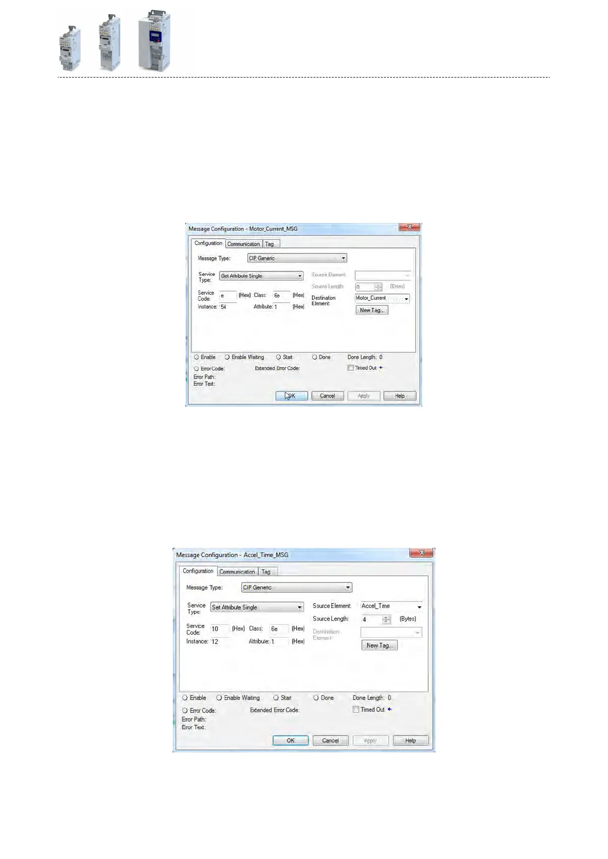
How to troubleshoot 24-V supply overload in Lenze i55AE155F Inverter?
- BBryan ThomasSep 13, 2025
To troubleshoot a 24-V supply overload in your Lenze Inverter, check the 24 V output and digital outputs for earth fault or overload.
How to troubleshoot 24-V supply overload in Lenze i55AE155F Inverter?
To troubleshoot a 24-V supply overload in your Lenze Inverter, check the 24 V output and digital outputs for earth fault or overload.
Provides essential starting guidance and safety instructions before proceeding with installation and commissioning.
Outlines fundamental safety precautions to prevent severe personal injury and material damage.
Describes the connection of the safety module, including critical warnings about automatic restart.
Provides critical warnings about incorrect wiring and settings during commissioning, emphasizing safety checks.
Details how to save parameter settings using the keypad or the EASY Starter software for mains failure protection.
Explains the meaning of "RDY" and "ERR" LEDs on the inverter for quick information on operating states.
Discusses how the inverter detects errors, protects components, and handles operating errors, warnings, and faults.
Describes inverter behavior when memory module data does not match hardware or firmware, covering automatic and manual loading/saving.
Explains how the rated mains voltage impacts the inverter's operating range and provides a table of settings.
Covers starting performance options like DC braking or flying restart circuit, and stopping performance methods like coasting or quick stop.
Describes the "quick stop" function as an alternative stop method for faster motor stopping, including its triggers and parameters.
Explains how to set motor data manually, covering parameters like pole pairs, rated speed, frequency, power, and current.
Details the different modes for closed-loop/open-loop motor control supported by the inverter.
Covers functions for further optimizing drive behavior, including V/f voltage boost, skip frequencies, and oscillation damping.
Covers options for improving total system power by selecting motors, tuning controllers, and performing automatic identification/calibration.
Covers various monitoring functions to protect the device or motor from destruction or overload.
Covers activating network control, network control words, status words, and data mapping for network registers.
Details basic settings for PID control, including activating PID, configuring analog inputs, and selecting setpoint sources.
Covers device commands for calling organizational functions like saving, loading, and resetting parameter settings.
Details the DC braking function, which generates braking torque by injecting DC current into the motor.
Covers write access protection for inverter parameters via keypad and EASY Starter, restricting parameterization.
Explains the function that decelerates the motor during power failure using rotational energy to maintain DC-bus voltage.
Explains the STO function for safely switching off the drive immediately and its operating principle.
Details how to configure the start, stop, and reversal commands flexibly via digital inputs, keypad, or network.
Covers configuration of triggers for basic motor functions like enable, run, quick stop, and reverse.
Explains how to change setpoint sources during operation using functions like analog inputs, keypad, network, presets, and MOP.
Explains how to reset an active error by using the "Reset Fault" function or cancelling the start command.