1-2
RLC-4 V1.79 Copyright © 1998 Link Communications Inc. 9/18/98
Step #3: Connecting Your Receivers to the RLC-4
The radios connect to the RLC-4 using a male DB-9 connector (included). The pin-outs are listed
below.
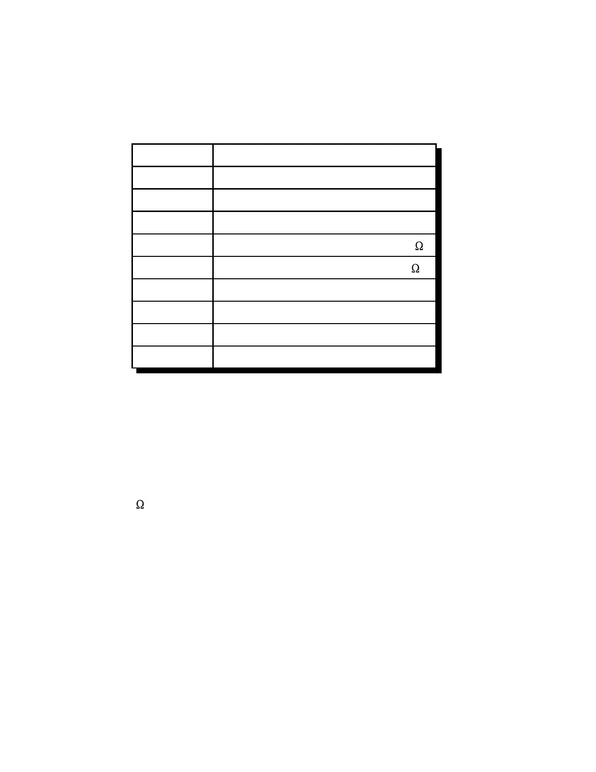
Pin Number Description
1 Ground
2 PL Input (From your PL Decoder)
3 PTT Output (To the Transmitter)
4 Audio Output (To the Transmitter) 600
5 Audio Input (From the Receiver) 10K
6 Ground
7 COR (From your Receiver)
8 Ground
9 Ground
Connecting the Receiver COR
The first step in connecting your receiver is to locate an active receiver signal. If the voltage goes
from a voltage above 3 volts to ground when a signal is present, the signal is active low. If the
voltage goes from ground to a voltage above 3 volts the signal is active high. The RLC-4 accepts
active low COR signals by default, but this can be changed for one or more of the radio ports with
command 013. The signal must be able to sink 4mA to ground. The input impedance of the RLC-4
COR input is 10K and it is diode clamped with internal pull-up resistors. This allows it to handle
input voltages of up to 40 volts without damage to the controller. The COR input must not go
below 0V (ground); this would damage controller’s COR/PL input . Using one of the supplied
DB-9 Male connectors, connect your COR signal to pin #7.
Connecting a PL Input (optional)
If you wish to use a PL (CTCSS) decoder on any of the receivers, its detect line can be connected
to pin #2 of the appropriate connector in the same fashion as the COR input. You will probably
also want to use the audio filter on the PL decoder board to filter the PL signal out of the receiver's
audio before it goes to the RLC-4.
 Loading...