14-7
RLC-4 V1.79 Copyright © 1998 Link Communications Inc. 9/18/98
139: Set Up the RLC-Icom Interface
The RLC-Icom interface allows the RLC-4 to control IC-900/901 band modules using the same
commands as are used for the Doug Hall RBI-1. This command tells the controller which interface
you are using (default is the RBI-1) and allows you to set up the RLC-Icom interface. This setup
procedure is not necessary for the RBI-1, since it will only support one band module being on at a
time.
Once you have set up the RLC-Icom with this command, you can use the RBI-1 commands
(Commands 141..143) as described.
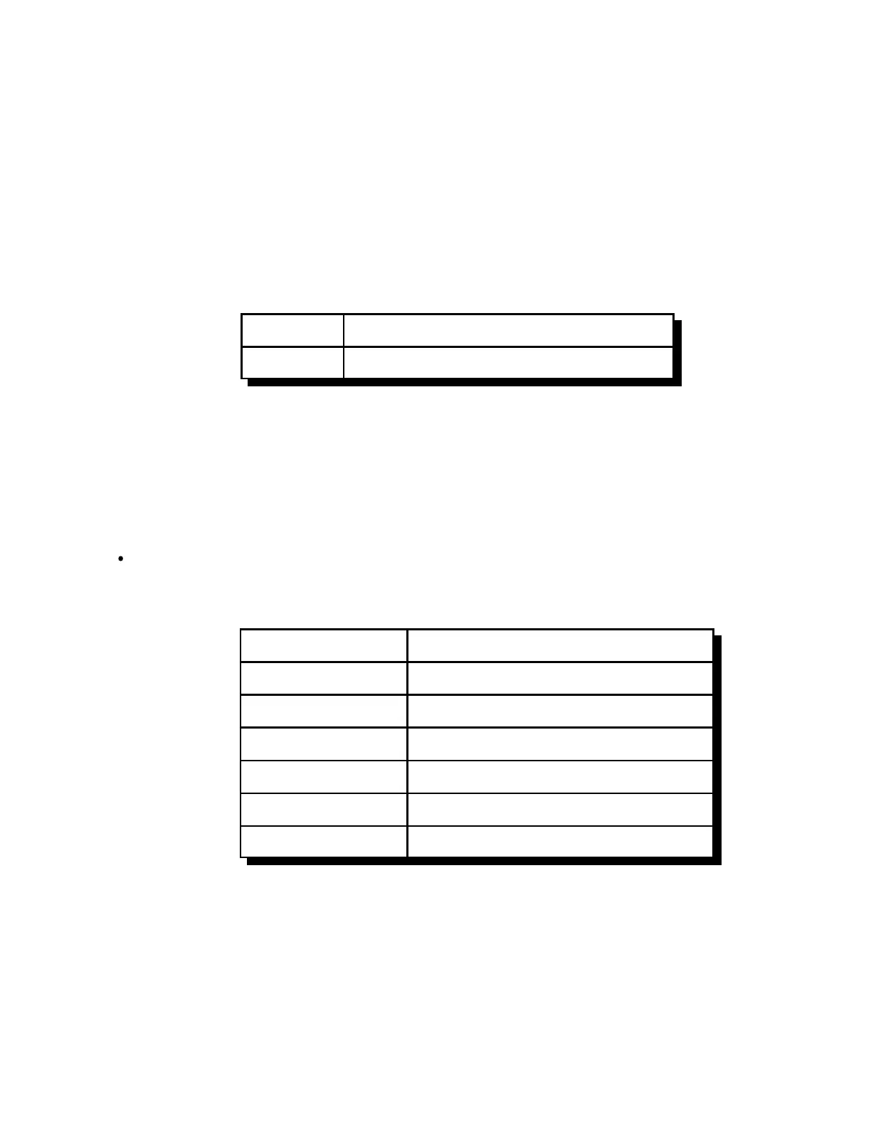
<139> 000 Set the controller for RBI-1 (the default)
<139> c ss Set the controller for RLC-ICM
Parameters:
- 139 is the default command name.
- C is the connector number on the RLC-ICM that the module you are setting up is plugged
into (1..4). Do not confuse this with the radio port number on the RLC-4.
- SS is the setup code described below
Procedure:
First tell the RLC-Icom which band module is plugged into each of its connectors. The
setup codes are listed in the chart below. You will need to execute command C139 once for
each setup code you wish to enter.
SS (the setup code) Description
00 28 Mhz Module
05 50 Mhz Module
10 140..160 Mhz Module
15 220 Mhz Module
20 430..440 Mhz Module
25 1200 Mhz Module (not currently active)
 Loading...