H-1
RLC-4 V1.79 Copyright © 1998 Link Communications Inc. 9/18/98
Appendix H: Using the LM335 Temperature Sensor
The RLC-4 supports the National Semiconductor LM335Z temperature sensor. The sensor
converts temperature into voltage. This voltage is read by the controllers ADC (Analog-Digital
Convertor) which allows the controller to read a voltage. When using the LM335Z sensor, the
sensor needs to be powered in order for the temperature to be read. Powering the sensor is
accomplished by turning the appropriate dip switch 'ON'. There is a pack of 8 switches, 4 for
power and 4 for the voltage dividers. The chart shows which switches must be off for the
temperature sensor to work.
Analog Input #1 Switch 1 ON Switch 5 OFF I/O Pin #5 (IN), Pin #17 (GND)
Analog Input #2 Switch 2 ON Switch 6 OFF I/O Pin #4 (IN), Pin #16 (GND)
Analog Input #3 Switch 3 ON Switch 7 OFF I/O Pin #3 (IN), Pin #15 (GND)
Analog Input #4 Switch 4 ON Switch 8 OFF I/O Pin #2 (IN), Pin #14 (GND)
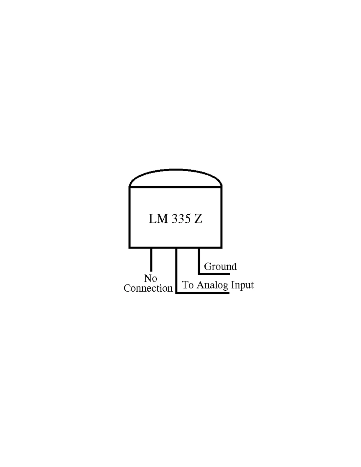
LM335Z Temperature Probe Connections Diagram
- If you have your temperature sensor hooked up backwards (+OUT switched with the -GND) you
will read ~0.6 volts across the sensor.
- Verify the appropriate resistor divider switch is OFF, and sensor power switch is ON. These
switches provide the power and control for the LM335Z.
- Voltage meter reading at the sensor measure: Temperature Celcius = (voltage*100)-273
 Loading...