1-6
RLC-4 V1.79 Copyright © 1998 Link Communications Inc. 9/18/98
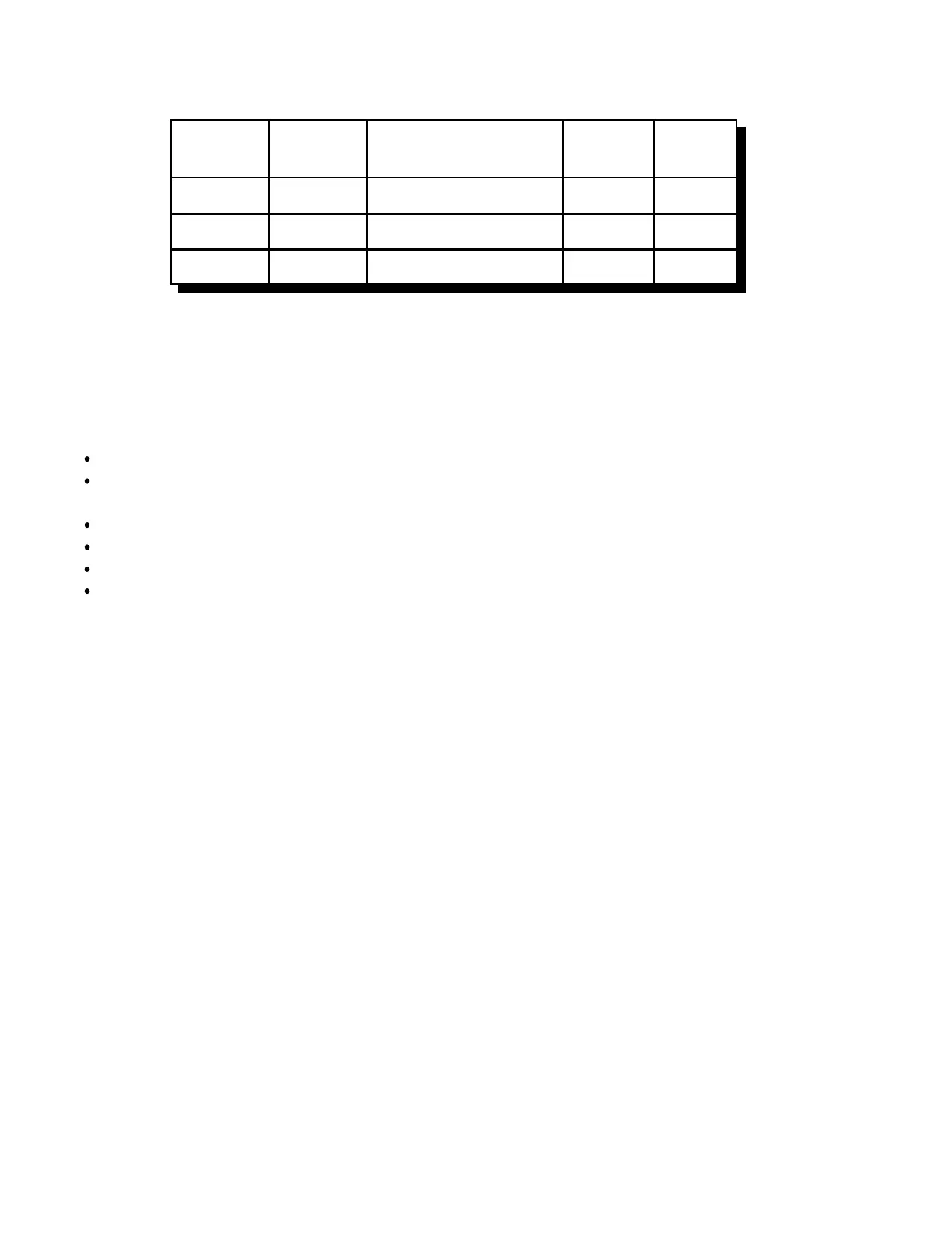
Computer to Modem Cable
Computer Computer Description Modem Modem
DB-9 DB-25 DB-9 DB-25
3 2 Data Out of Computer 3 2
2 3 Data Into Computer 2 3
5 7 Ground 5 7
You will not need to connect the modem to the phone line to enter these setup commands. Load
your communications program and set the comm port to talk to the external modem (it will
probably be set for the internal modem when you start). Enter "ATZ" (without the quotes) and
press enter. You will see an "OK" response if everything is hooked up right. Then enter (without
the quotes, pressing enter after each command):
"AT&F" to set everything to factory defaults.
"ATS0=3" to make the modem answer after 3 rings or "ATS0=0" to keep the modem from
answering at all.
"AT&K0" to disable local flow control (the controller doesn't support it).
"ATE0" to disable local echo.
"ATQ1" to keep the modem from sending result codes.
"AT&W" to store the settings to the modem's non-volatile memory.
If you are unable to disable your modem's flow control in software, you may have to put jumper
wires between some of the pins on its DB-25 connector to fool it. Shorting pins 4 and 5 together
and pins 6, 8 and 20 together should fool the flow control into working.
RS-232 Signals and Interfacing
The RLC-4's input and output is the RS-232 standard, ±12V. The pinout is standard for a 9-pin
serial connector. To connect to a terminal or computer's 9-pin serial connector, use a straight-
through cable (not a null modem) with at least pins 2, 3, and 5 connected. To connect to a
computer with a 25-pin serial connector, you can use a standard 9 to 25-pin converter or wire your
own cable. To wire your own, connect the RLC-Club's pins 2, 3, and 5 to the computer's 3, 2, and
7 respectively.
If you are connecting the controller to a modem, you will need to swap pins 2 and 3 relative to how
you would connect it to a computer or run your cable through a null-modem adaptor. This is
because master and slave devices (DTE and DCE devices) are wired differently. When hooking the
controller and a modem (both slave devices) together, you have to adjust accordingly. The
following chart summarizes the four different types of cables you may need.
 Loading...