Page 47 of 88 TP1A072–3 English
Aug 2017
Linx 10 Operating Manual —
Line and message settings
Linx 10
6 Measure the length of the printed calibration message. This value is the distance between the
outer edges of the end arrows, shown by the red dots in Figure 37 on page 46. For reference,
when the length of the calibration message is 100 mm (plus or minus 1 mm), the line speed is
accurate.
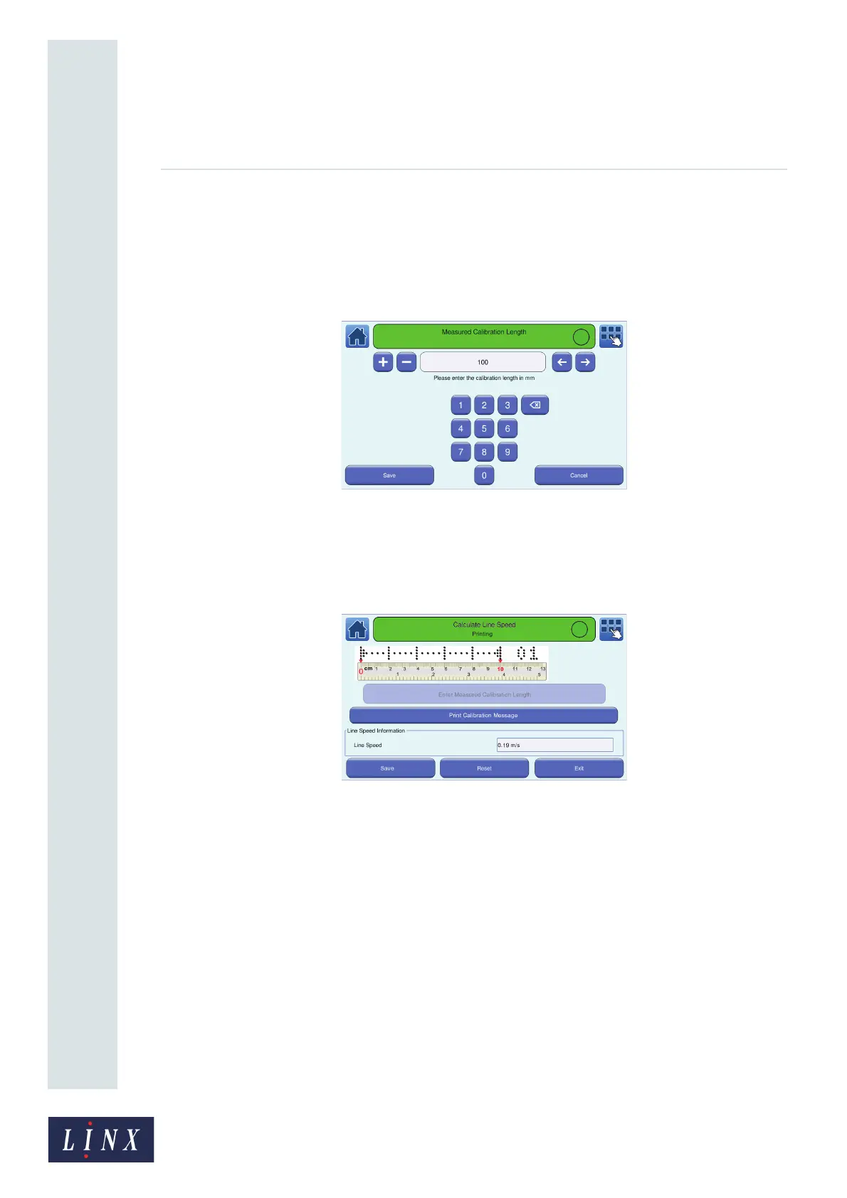
7 Touch the Enter Measured Calibration Length button to display the Measured Calibration
Length screen.
Figure 39. Measured Calibration Length screen
8 Enter the measured calibration length (for example 75 mm) and touch the Save button. The
printer calculates the line speed from the entered measurement and displays the Calculate
Line Speed screen. The printer displays the calculated line speed in the “Line Speed
Information” box.
Figure 40. Calculate Line Speed: line speed calculated screen
9 Touch the Stop button to pause the print or touch the Reset button to return to the previous
line speed value. Touch the Save button to save the new calculated line speed.
Calculate Encoder Pitch
NOTE: Make sure that a shaft encoder is installed on the production line and the encoder is
connected to the printer.
1 Set the printer to Shaft Encoder mode (see ‘Speed Mode’ on page 42).
89146