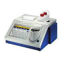
LB 9507 Chapter 16: Block Diagrams
16-1
16. Flow diagram of the measurement procedure
The following information provides a guide to the measurement
procedure and the menu system of the Lumat software.
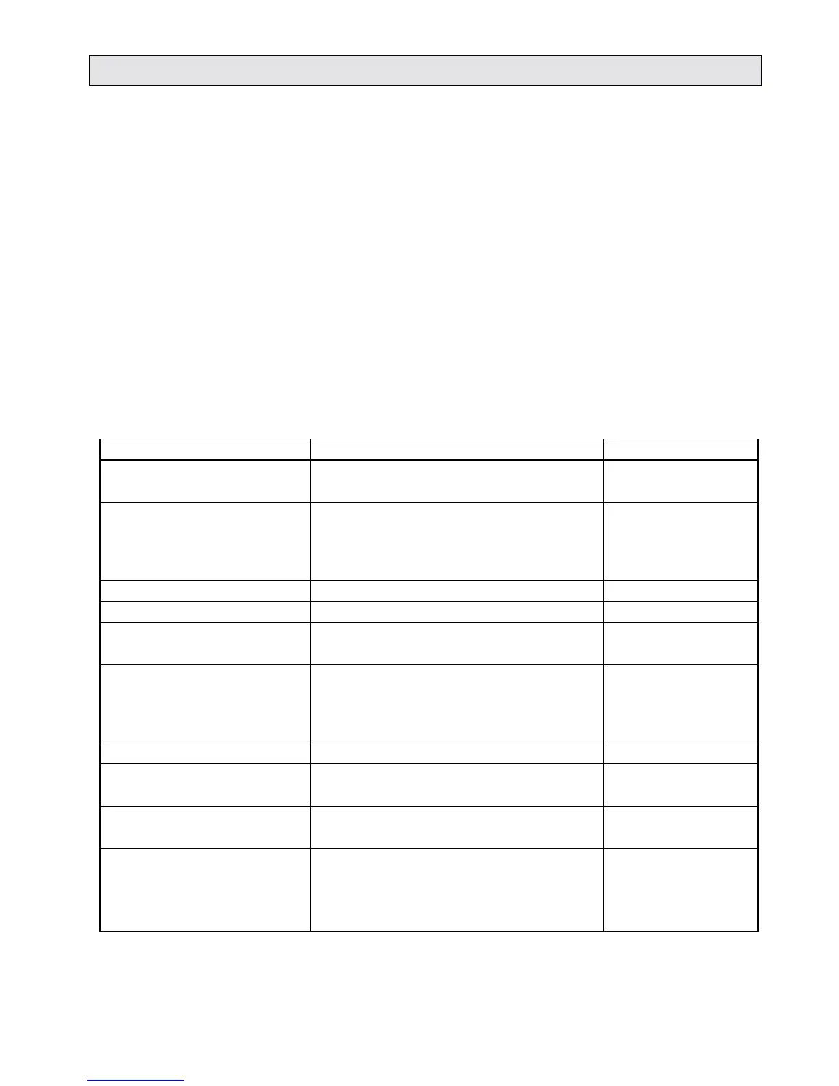
The following table is a schematic representation of the
measurement procedure and user actions, instrument actions and
instrument displays.
The second diagram shows the assignment of functions to
menus, providing an overview of all software functions.
The third diagram shows the procedure for creating
measurement protocols.
Schematic representation of the measurement procedure
Display User action Instrument action
1 SAMPLE 1 TUBE 1
INSERT TUBE... Load the 1st tube
2 SAMPLE 1 TUBE 1
START
Press <start> button
Rotor turns the 1st tube
in the measurement
position
3 MEASURING... Measuring tube 1
4 MEASUREMENT (RLU) 133 Displays results
5 SAMPLE 2 TUBE 2
INSERT TUBE... Load the 2nd tube
6 SAMPLE 2 TUBE 2
START
Press <start> button
Rotor turns the 2nd tube
in the measurement
position
7 MEASURING... Measuring tube 2
8 MEASUREMENT (RLU) 137 Displays results
REMOVE TUBE Remove the 1st tube
9 SAMPLE 3 TUBE 3
INSERT TUBE... Load the 3rd tube
10 SAMPLE 3 TUBE 3
START
Press <start> button
Rotor turns the 3rd tube
in the measurement
position