
R
Ronald BentleyJul 31, 2025
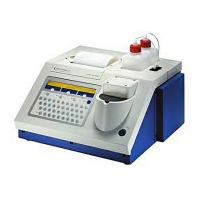
Why is the background effect too high on my LUMAT LB 9507?
- DDiamond WellsJul 31, 2025
If the background effect is too high in your LUMAT Laboratory Equipment, first check the measurement protocol for any incorrect background effect entries and change the protocol entry accordingly. Other potential causes include malfunctioning sealing elements, a contaminated measurement chamber, a defective photomultiplier or electronic unit, or fan failure; in these cases, it is best to call Technical Service. Additionally, ensure that sample tubes are not stored in direct sunlight to avoid phosphorescence and that the sample tubes are suitable and not contaminated. For more details on suitable sample tubes, see chapter 1.