Chapter 2: Design of the Lumat LB 9507
2-6
2.4 Measurement Unit
The measurement unit is located to the right of the keyboard (see
Fig. 2-1, [9]). The sample chamber is protected against dust by a
semi-circular cap. The measurement chamber is located in the
instrument itself and can only be accessed by removing the cover
of the instrument (see Fig. 2-2).
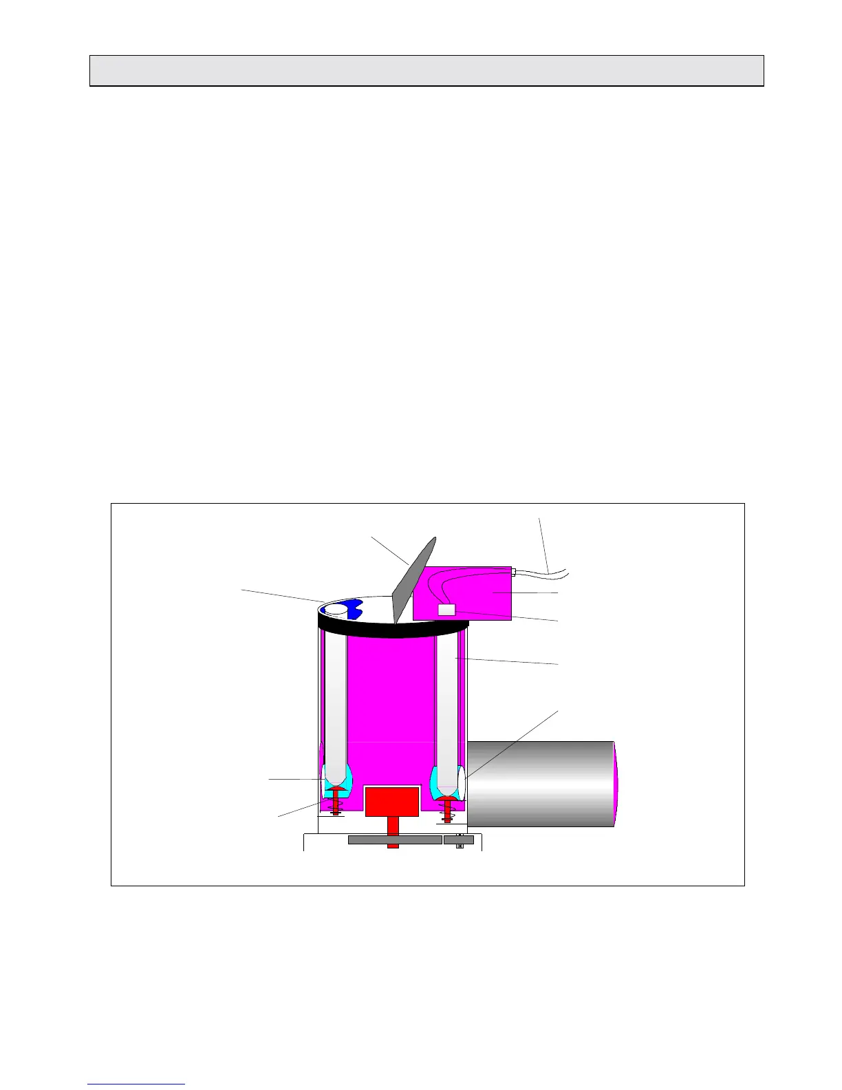
Structure and function The following diagrams (Figs. 2-5 to 2-8) explain the structure and
function of the measurement unit.
The measurement unit comprises the following components:
●
●●
● a black, light-proof measurement chamber casing
●
●●
● the tube transport rotor inside this casing, incorporating 2 holes
for holding sample tubes and a mirrored measurement
chamber
●
●●
● a tube detector
●
●●
● a stepping motor for rotating the rotor
●
●●
● an injector head in the measurement unit lid
●
●●
● an opening for the photomultiplier at the rear.
Injector lines to the pumps
Measurement chamber cap
Fig. 2-5: The structure of the measurement unit (schematic illustration)
Loading position
Mirrored measurement
chamber
Spring pin for lifting
the tube in loading
position
Injector head
Injector tips
Measurement
position
Meas. chamber opening
for