Chapter 2: Design of the Lumat LB 9507
2-12
Injector lines
The connections for the injector lines on the instrument are
defined as 1 (injector 1) and 2 (injector 2). Use these designations
when programming measurement protocols.
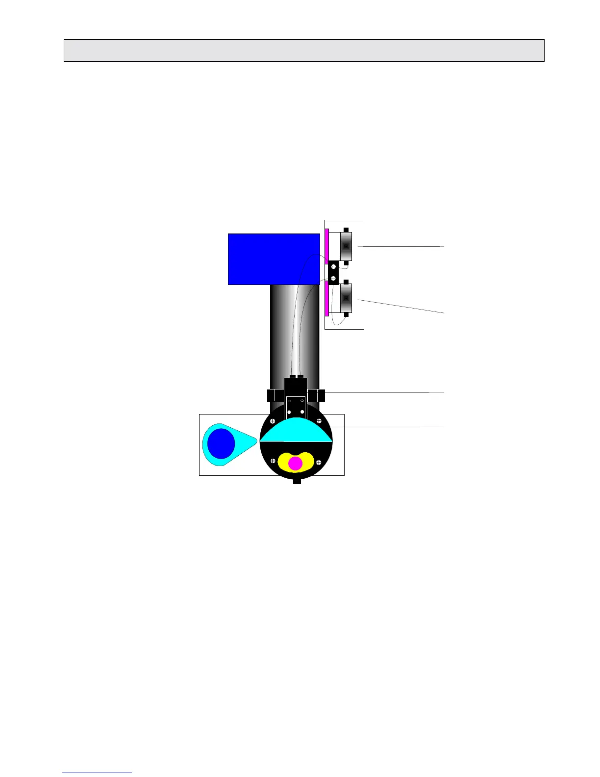
The injector lines lead to the corresponding pumps, and from
there to the injector head. The right hand connection on the
injector head comes from injector pump 1 (see Fig. 2-11).
Fig. 2-11: The connections injector pumps / injector head
Injector pump 2
Injector pump 1
Injector head
Measurement
chamber