6-13
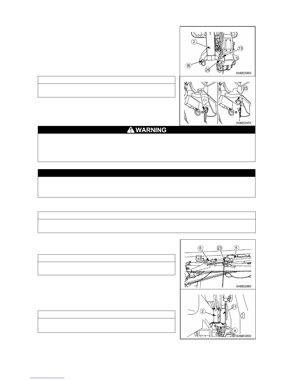
3. Once the connection hole of the No.1 Fly-jib (2) and the hole (A)
of the bracket (26) on the right side of the Main boom tip are
aligned, insert the position pin (15) to the hole then secure it with
the linchpin (25).
Detach the linchpin (25) for the position pin (15) from the hole for
storage at the boom tip and apply to the position pin (15).
• Do not remove the position pin (16) from the fly-jib bracket A (21) until the position pin (15) is
fully inserted into the hole of the bracket (21). Incorrect fitting order may cause a serious
hazard.
• The position pin (15) must always be inserted downward from upper side. If it is inserted from
the underside it could drop out allowing the Fly-jib to collapse causing a serious hazard.
When the position pins (15) and (16) are fitted into both holes of the bracket (26) on the right
side of the Main boom tip and Fly-jib bracket A (21), Main boom telescoping must not be
operated. This operation will critically damage the Fly-jib and Main boom.
4. Start the engine and then operate the boom to hold it level.
To make the boom level, ensure that the boom angle display of the moment limiter indicates "0".
In addition, visually check the boom is level.
5. Set the attached lever block (23) between the tilt angle adjuster
outer rod (5) and inner rod (6).
Lever block (23) handling will be easier, when you set the lever
side to the outer rod side (5).
6. Wind up the lever block (23) to provide the clearance (a)
between the bracket of No.1 Fly-jib (2) and the stowage bracket
(21).
The lever block (23) is also required for changing the Fly-jib tilt
angle. Leave the lever block (23) attached, but do not detach it.