53
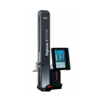
Mahr GmbH • Digimar 817 CLM
4.4.2 Measuring the perpendicularity error
Determine the perpendicularity error with either an incremental
probe or a digital indicator
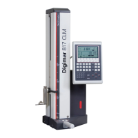
– Connect the incremental probe P1514 H via the INPUT 2
interface or the digital indicator
1081, 1086 / 87 to a 16 EXr data cable via. the INPUT 1
interface.
– Press the menu key and under the perpendicularity error select
the required input.
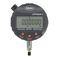
Input 1: (e. g. 1086 / 1087) Digital indicator
Input 2: P1514 H Incremental probe
A maximum of 500 measuring points can be accepted. Depending
upon the speed and the measuring instrument (350/600/1000 mm)
the number of measuring points and the set measuring track can
alter accordingly.
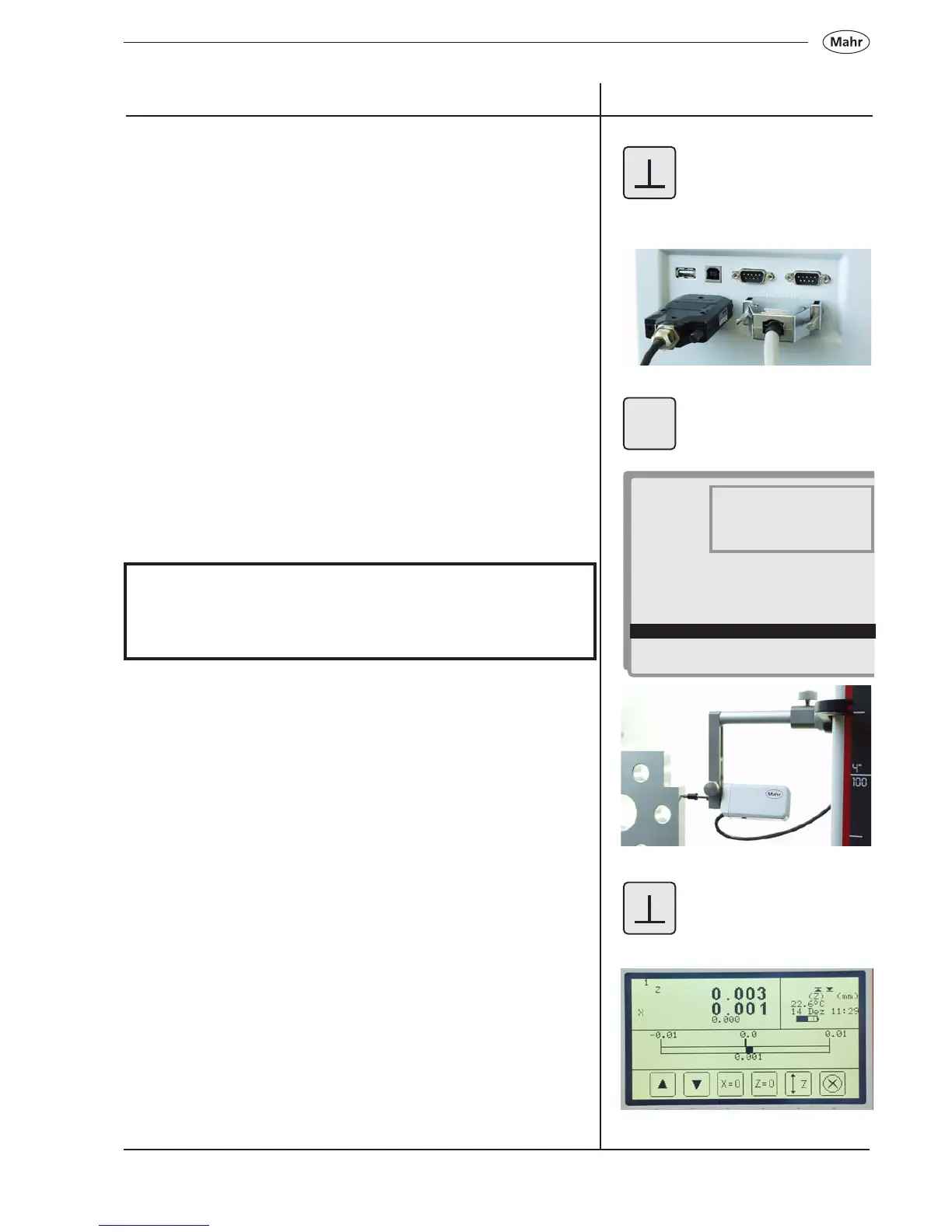
– Mount the probe into the holder on the measuring carriage
– Select the perpendicularity error function
Description / Sequence Symbols / Pictures
MENU
1 23456
1 = Start an upwards measurement
2 = Start an downwards measurement
3 = Set the X-value to zero
4 = Set the Z-value to zero
5 = Enter the measuring path
6 = Abort
1. <-_______
2. Standstill-time
3. Contacting speed
4. Resolution
5. mm/inch
6. Language
7. Date and time
8. LCD settings
9. Beep ON/OFF
10. Auto – off time (min)
11. Quick-Mode
12. Perpendicularity
13. Data and printer
14. Advanced settings
1. Input 1 (OPTO-RS232)
2. Input 2 (P1514 H)
 Loading...