126
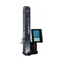
Mahr GmbH • Digimar 817 CLM
9.1 Description of interfaces
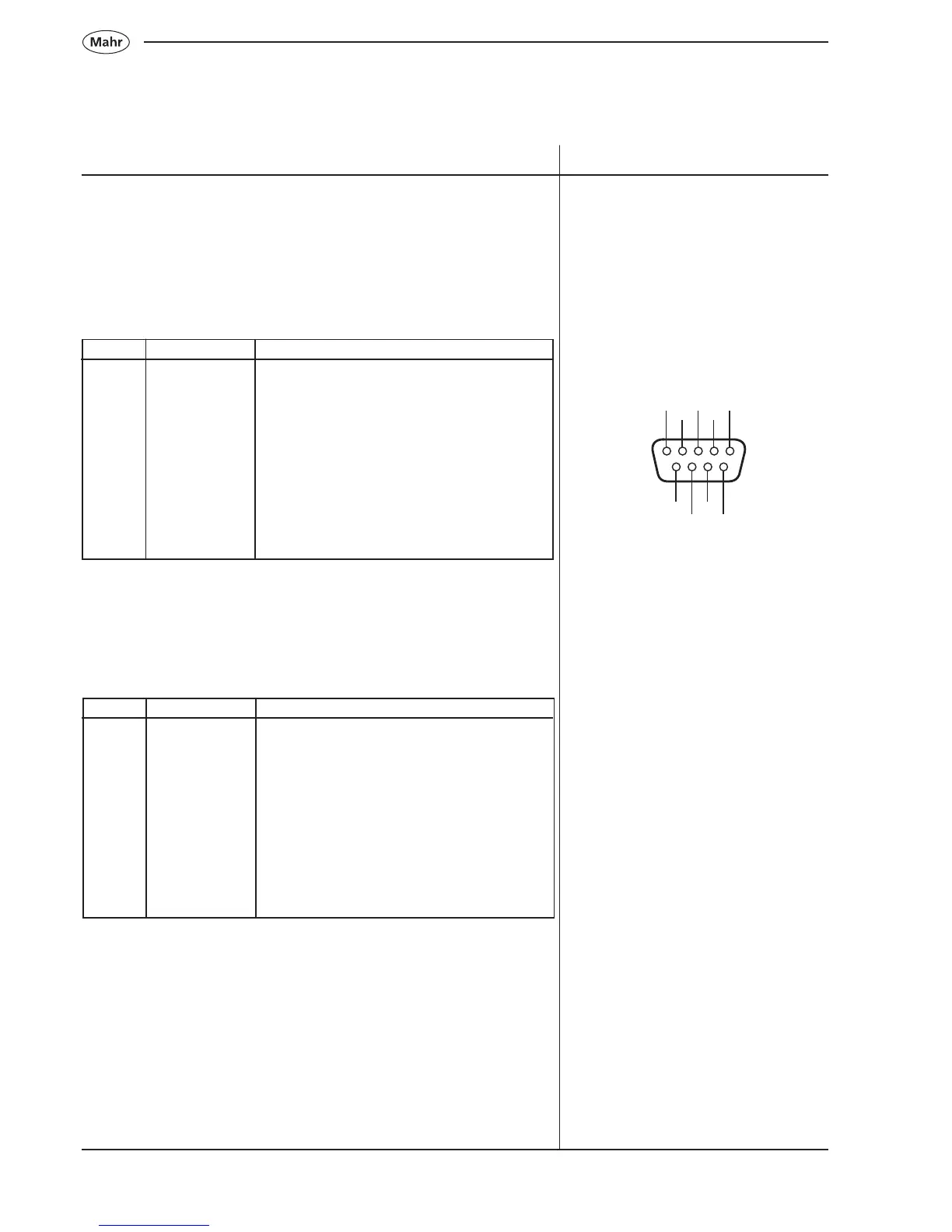
9.1.1 Pin assignment for RS232 Input
RS232 input for hand measuring instruments:
Pin-No. Identification Description
1 Not connected
2 RXD Data input from a hand meas. instrument
3 GND Ground
4 Request Output for Data-Request
5 NC Not connected
6 NC Not connected
7+V +8 V Supply voltage
for Opto-Interface
8 NC Not connected
9 NC Not connected
Description / Sequence Symbols / Pictures
9.1.3 USB interface Type A
In a USB cable four wires are required, one pair of wires transfer the
data and the other pair supplies the connected instrument with a power
supply of 5 V. Instruments that have a USB specification may obtain
between 100 mA or 500 mA from the USB port, depending on how much
power the port can supply. Instruments that have a performance of up to
2.5 W can also be supplied via a Bus.
1
2
3
4
5
6
7
8
9
9.1.2 Pin assignment for RS232 Output
RS232 to a PC output:
Pin-No. Identification Description
1 NC Not connected
2 RXD Receive Data
3 TXD Transmit Data
4 DTR Data Terminal Ready
5 GND Ground
6 DSR Data Set Ready in
7 RTS Request to send
8 CTS Clear to send in
9 NC Not connected
9. Communication
 Loading...