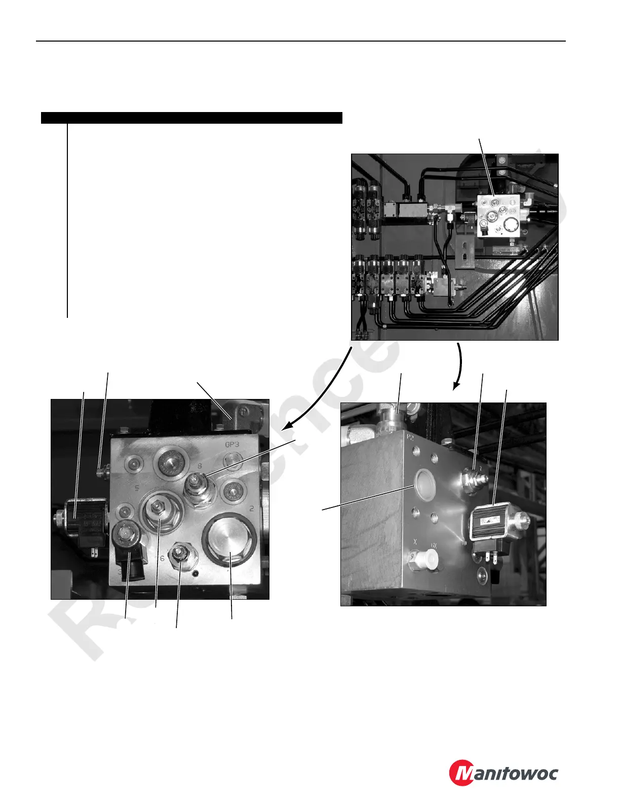
Left Side
Item Description
1
Accessory System Manifold for MAX-ER, Engine Cooling Fan,
Accessory High Pressure, and Accessory Low Pressure
2
35 to 345 bar (500 to 5,000 psi) Accessory System Proportional Relief
Valve HS-68
3 214 bar (3,100 psi) Relief Valve Fixed
4 24 volt, 3-way, 2 Position Hydro Fan Solenoid Valve
5 Logic Relief Element Set at 0.8 bar (12 psi)
6 Pressure Reducing Valve Cartridge Set at 40 bar (580 psi)
7 Pressure Relieve Valve Cartridge Set at 345 bar (5,000 psi)
8 Sequence Valve with Internal Pilot
9 P2 Port for Pressure Supply from Variable Accessory Pump
10 P3 Port for Pressure Supply from Fixed Gear Accessory Pump
11 OUT Port to Fan Motor
12 P1 Port (not shown) Pressure Supply to Accessory and MAX-ER
13 P4 Port (not shown) Pressure Supply to Lower Accessory System
14 T Port (not shown) Return to Tank
15 P5 (not shown) Supply to Accessory System Pressure Sender
1
2
2
3
3
4
5
7
6
8
9
10
11
P2439a
P2350a
P2351a
FIGURE 1-5 continued