Manitowoc Published 06-24-16, Control # 241-01 3-65
2250 OPERATOR MANUAL OPERATING CONTROLS AND PROCEDURES
4. MAX-ER State/Faults (total of number(s) listed):
1 = Tray high on left side (CWT level is more than 3.0
degrees)
2 = Tray high on right side (CWT level is less than -3.0
degrees)
4 = Derived that strap cylinder loads are both 9 071,9 kg
(20,000 lb). Value 4 does not trigger a MAX-ER fault.
8 = Not used
16 = Left rod side pressure transducer out of range
(below 0.6 or above 9.0 V)
32 = Right rod side pressure transducer out of range
(below 0.6 or above 9.0 V)
64 = Differential pressure (one side taking 144.8 bar
[2100 psi] more than other side)
128 = Piston pressure transducer out of range (below
0.6 or above 9.0 VV)
5. MAX-ER controller communication status: 0 = Good.
Any other number indicates a problem with MAX-ER
controller communication to the crane controller.
Contact the Manitowoc Crane Care Lattice Team.
6. Right strap cylinder rod side pressure (0 to 207 bar [0 to
3,000 psi])
7. Left strap cylinder rod side pressure (0 to 207 bar [0 to
3,000 psi])
8. Strap cylinder piston side pressure (0 to 207 bar [0 to
3,000 psi])
9. Strap cylinder command:
0 = Idle
1 = Raise tray
2 = Lower tray
A1 (handles)
The variable control handle output voltage is represented in
the controller by a number between 0 (0 V) and 255 (10 V).
The diagnostic screen A1 displays this number for each of
the control handles/pedals. The normal operating outputs of
the handles range from the following:
• Approximately 38 (1.5 V) to 120 (4.7 V) for lower/
reverse/right. Some dual-axis handles (joysticks) are
internally limited and will not put out the full range stated.
• Approximately 136 (5.3 V) to 215 (8.5 V) for raise/
forward/left. Some dual-axis handles (joysticks) are
internally limited and will not put out the full range stated.
• A switch opens when the handle is in the neutral range
(4.7 to 5.3 Vs). In the neutral range, the screen reads 0.
Banks:
1. Handle 1—Right rear or front load drum
2. Handle 2—Left rear or rear load drum
3. Handle 3—Boom/luffing/mast hoist
4. Handle 5—Right track
5. Handle 6—Left track
6. Handle 4—Swing
7. Handle 7—Auxiliary load drum or luffing hoist with
independent pump
A2 (programmer’s screen)
D1 and D2 (digital outputs and inputs)
The status of the digital outputs from the controller and the
inputs to the controller are displayed in several banks in
screens D1 and D2. Each bank can indicate the state of up to
eight individual digital inputs or outputs.
NOTE: 1 through 8 = Bank number
X = Corresponding digital screen number (1 or 2)
Each individual input/output is assigned a number (identifier)
in the binary system (powers of two). The identifiers of all
inputs/outputs that are on (active) are added to a total in
each bank. Thus, the number displayed for each bank is the
sum of all identifiers of the inputs/outputs that are on (0
through 255). With this system, each possible on/off
combination per bank has a unique total.
For identification of the digital outputs and inputs (and the
crane components connected to them), see Table 3-10
and
Table 3-11
.
To determine the state of the individual inputs/outputs in a
bank, find the number displayed for the bank in the first
column in Table 3-12
. In the corresponding row, the identifier
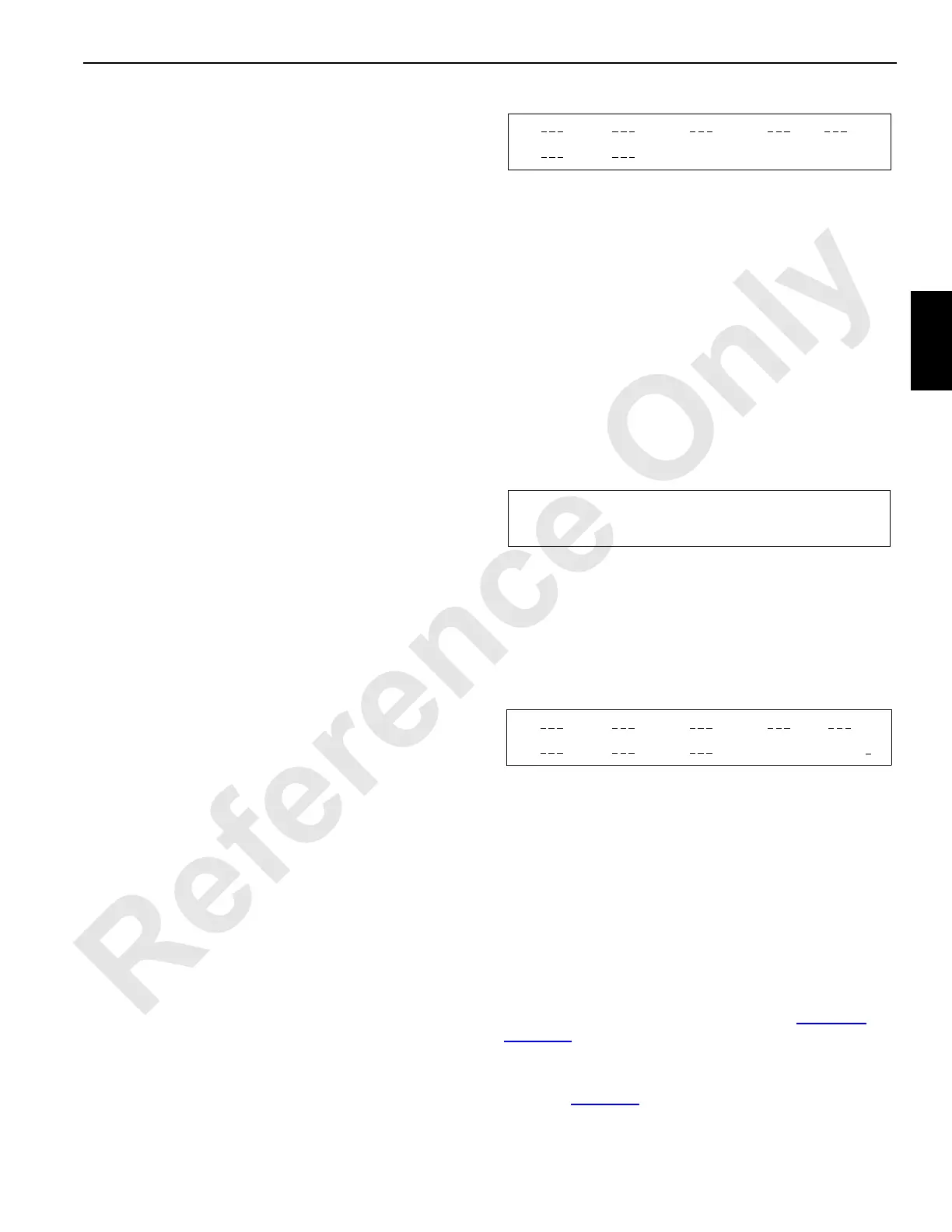
A2
Disregard information screen. For
factory programmer’s use only.
FIGURE 3-51