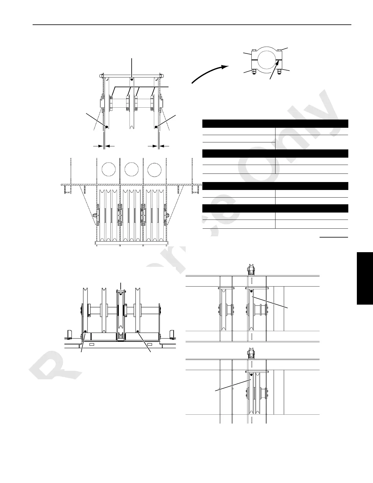
Left Rear
Drum
Boom Top
Guide Sheaves
Rear View
123 456 789
Tighten each side equally to provide an equal gap.
NOTE: Hand position the clamps tight against the
bearing. Before tightening the bolts, make sure
the sheave turns freely. Tighten the bolts
lubricated with SAE 20 oil to 163 Nm (120 ft-lb).
Clamp
Bolt
Nuts
Lock Washer
Right Rear
Drum
LEFT REAR DRUM GUIDE SHEAVE
Rope routed to sheave Dimension A
1
Sheave tight against side frame
2
RIGHT REAR DRUM GUIDE SHEAVE
Rope routed to sheave Dimension A
8
52 mm (2-1/16 in)
1
1
This position requires two sets of clamps.
RIGHT REAR DRUM GUIDE SHEAVE
Rope routed to sheave Dimension B
9 Sheave tight against side frame
LUFFING HOIST DRUM GUIDE SHEAVE
Rope routed to sheave Dimension C
Upper boom point
Sheave centered
1
1
This position requires two sets of clamps.
C
A
or
B
Lower Boom
Point Sheaves
Rear View
A1276
A616
A
• = Wire Rope
Avoid Damage to the Wire Rope:
• Route the rope as shown
• Position the boom top guide sheaves as
shown
Clamps
Luffing Hoist/
Auxiliary Drum
Luffing Hoist/
Auxiliary Drum
Luffing Hoist/
Auxiliary Drum
FIGURE 4-75 continued