OPERATING PROCEDURES TMS9000-2 OPERATOR MANUAL
4-56
Published 02-21-2019, Control # 611-05
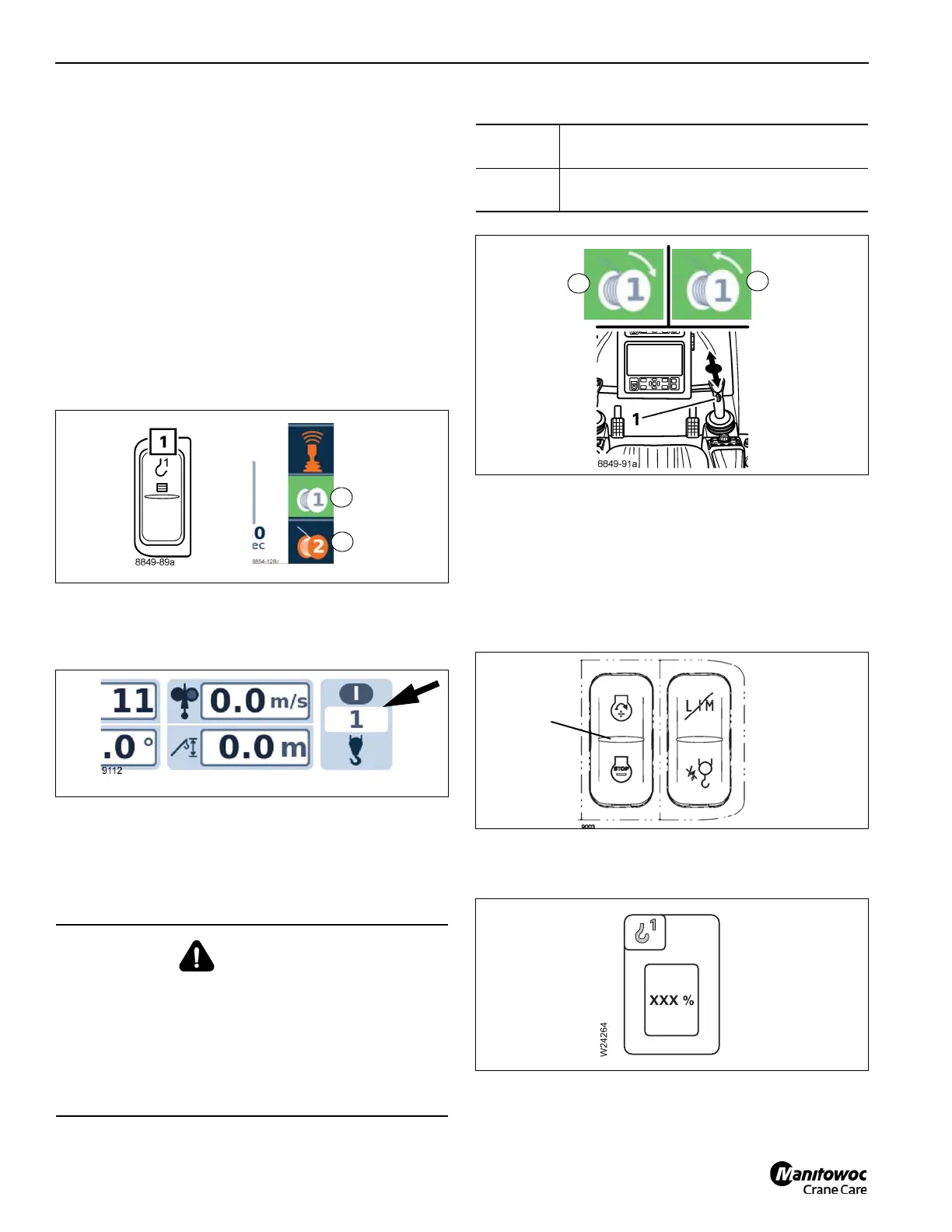
Switching on the main hoist
After the ignition is switched on, all of the power units will be
switched off and the lamps in the corresponding buttons will
light up only dimly.
• Check whether the auxiliary hoist is switched off and
therefore secured against unintentional operation.
NOTE: Be aware that the auxiliary hoist could two-block
when operating the main hoist.
- Symbol (3, Figure 4-86) must be red.
• Press the button on the right armrest (1, Figure 4-86)
once.
- Symbol (2) is green when the main hoist is switched
on.
• Check that the current reeving (Figure 4-87) of the main
hoist is displayed, e.g. 1. Correct the reeving if
necessary, refer to Entering the reeving, page 4-48.
Lifting and lowering
You can adjust the sensitivity of the control levers to suit the
operating conditions, refer to Setting the characteristic
curves for the control levers, page 4-84.
When the hoist drum is turning, you will notice a pulse on the
rotation indicator (1, Figure 4-88).
You can regulate the speed by moving the control lever or
changing the engine speed.
You can set the desired engine speed (idling speed) with
button (1, Figure 4-89), refer to Engine Idle Increment/
Decrement Switch, page 3-7.
You can limit the maximum hoist speed (Figure 4-90), refer
to Limiting the power unit speeds, page 4-85.
You can switch on high-speed mode for a higher speed
(Figure 4-91), refer to High-speed mode, page 4-80.
WARNING
Rope Damage Hazard!
Use of hookblocks that do not have sufficient overhaul
weight could result in spooling problems causing damage
to the rope. Death or Serious injury could occur if the rope
breaks. Always ensure that the overhaul weight is
sufficient to keep tension on the rope even when no load
is being lifted.
8854-128c
FIGURE 4-86
8849-89a
2
3
Raising:
Pull the control lever to the rear – symbol (3,
Figure 4-88) is displayed.
Lowering:
Pull the control lever to the front – symbol (2)
is displayed.
 Loading...


