Operation
135
5
MP01C050
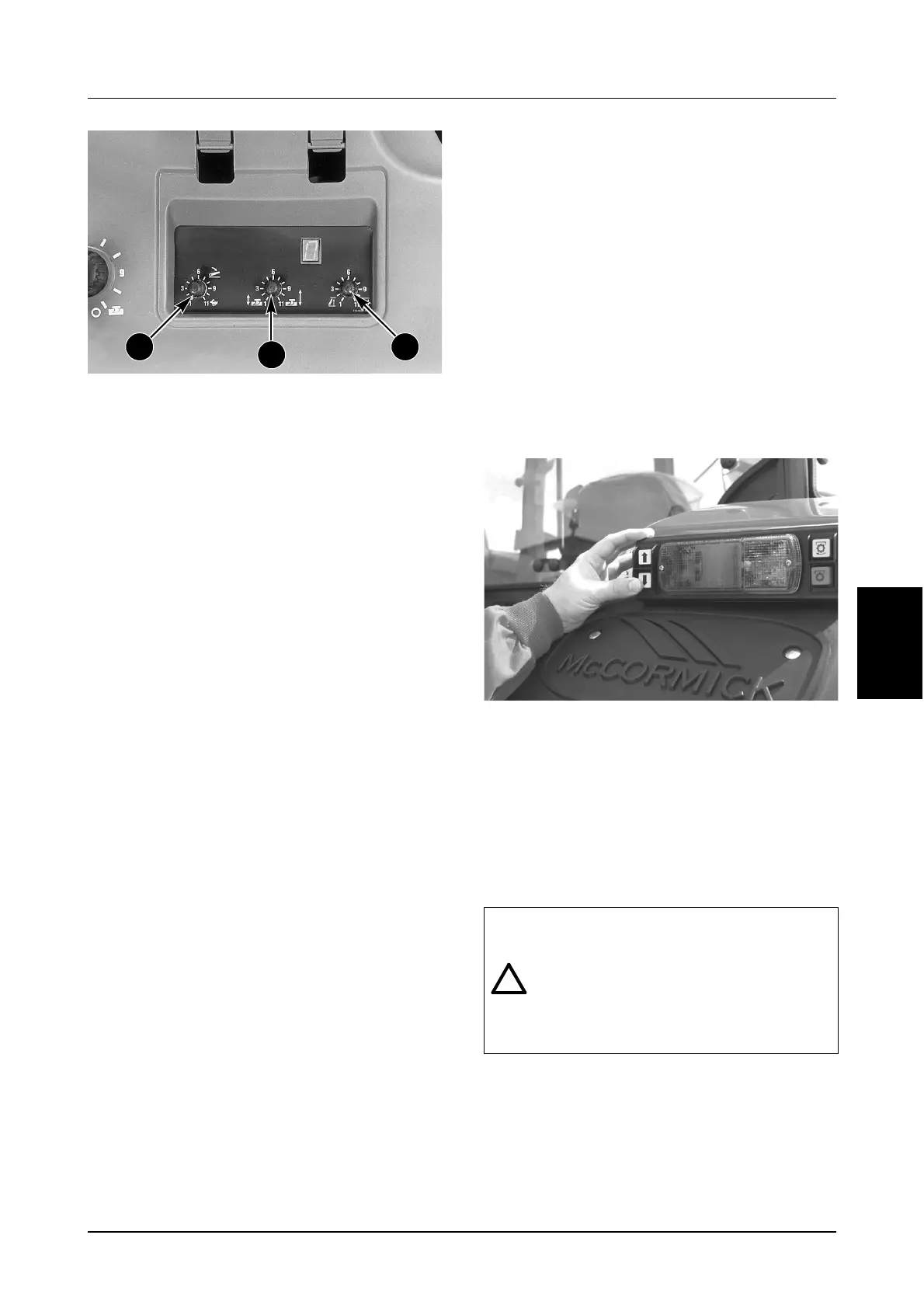
5. Drop Speed Control
This knob is used to adjust the lowering speed of
the hitch when using either the UP/DOWN
SWITCH or the POSITION CONTROL knob. Set
the DROP SPEED to fast (fully clockwise) for light
weight implements, and slow (fully
counterclockwise) for heavy implements such as
ploughs. This control can be over-ridden by
double clicking and holding the UP/DOWN
SWITCH in the MOMENTARY position.
6. Travel Control
This knob is used to adjust the amount of hitch
movement (depth variation) allowed in the LOAD
CONTROL MODE. Turning the knob clockwise
will increase the hitch movement. This allows
closer control of the load on the tractor and
enables the hitch to follow soil contours better.
Turning the knob counterclockwise will decrease
the amount of hitch movement. Set the control in
the lower range when using semi-mounted
implements or on flat terrain where the amount of
hitch movement can be restricted without
affecting performance.
7. Upper Limit Control
This knob is used to adjust the maximum
transport height of the hitch. It limits the transport
height when using either the UP/DOWN SWITCH
or POSITION CONTROL knob. A setting of “1”
allows the hitch to raise only half the way, while a
setting of “11” allows full transport height to be
reached. This control can be used to limit hitch
height with fully-mounted PTO driven implements
where the angle of the Implement Input Driveline
(IID) joints need to be limited to prevent noise,
chatter and damage due to excessive angles.
Turning the knob clockwise increases the
transport height. Turning the knob
counterclockwise decreases the transport height.
IMPORTANT: When using the Automatic Hitch the
UPPER LIMIT STOP MUST ALWAYS be rotated
fully clockwise to the stop position (position “11”).
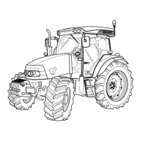
8. Operation of External Hitch
Switches (If Equipped)
The external switches can be used to raise or
lower the hitch from outside the tractor. This
can be useful for making small adjustments
when connecting implements to the 3 point
hitch.
IMPORTANT: On tractors equipped with an
Electronic Transmission the right hand door
MUST be closed before attempting to enable
the hitch.
Always operate the remote switches according to
the following procedure:
Move the shuttle lever to the NEUTRAL position.
Engage the park brake.
MD04G024
Press the top switch to raise the hitch. Press the
bottom switch to lower the hitch.
When the switches are released, the hitch will stop
at the selected position.
If both switches are pressed together the hitch will
stop. When the switches are released, the system
will reset in approximately one (1) second. The
hitch switches can be used in the normal manner.
NOTE: For safety purposes, when either of the
external hitch switches are operated the internal
cab hitch controls are automatically disabled. It will
be necessary to re-active the hitch before you can
operate the internal hitch controls.
6
5 7
WARNING: Stand well clear of the linkage
or implement when operating the external
controls or injury can result from contact
with moving parts.
Watch for possible pinch points between
the implement and tractor when the hitch is
moved.
1
2