7. Click each tab across the top of the window and look for a reading of Passed. A Passed
reading indicates all valves are in a proper state for operation. If any test shows a Failed
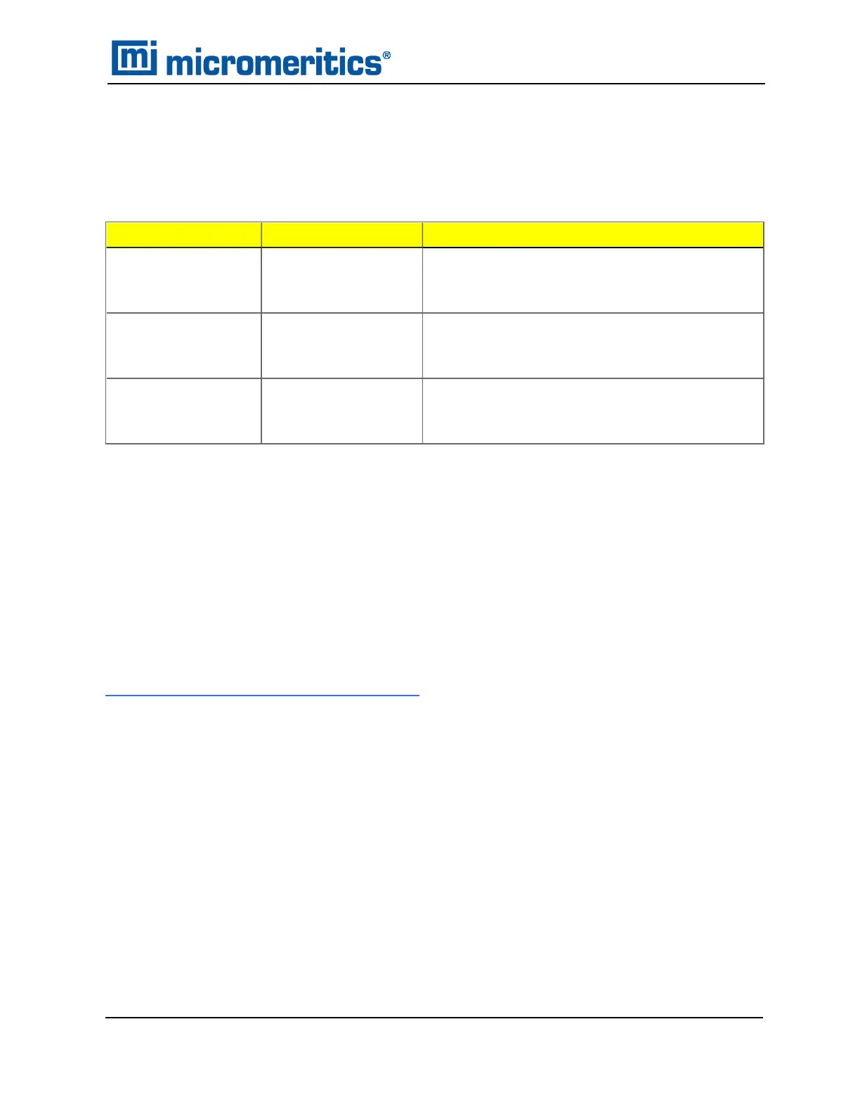
reading, refer to the following table to help determine the location of the gas leak.
Tab
Test If Failed status, then...
Gas Line to Inlet
Port [n]
Test 1
Gas Line to Gas Cylin-
der Test
This test will show a reading of Failed if any of the
other tabs has a Failed reading. Correct the
failed connection and rerun the test.
Gas Line to Inlet
Port [n]
Test 2
Gas Line to Isolation
Valve Test
Check for a leak between the gas line and the
isolation valve. Correct the problem and rerun
the test.
Gas Line to Inlet
Port [n]
Test 3
Isolation Valve To
Cylinder Leak Rate
Check for a leak between the isolation valve and
the gas cylinder. Correct the problem and rerun
the test.
Corrective Action
If a test reports as failed, one or more valves is not in the proper position. Set the valves, then
ensure the appropriate pressure is displayed on the low pressure gauge.
If re-running the test, close the gas cylinder valve before starting the test.
1. Click Close to close the test report. Click Close again to close the test.
2. Repeat steps 1 through 8 for each gas line attached to the analyzer.
ENABLE MANUAL CONTROL
Unit [n] > Enable Manual Control
Show Instrument Schematic on page2 - 20
Use Enable Manual Control to enable the manual control of certain system valves and pump com-
ponents on the analyzer schematic. When this option is enabled, a checkmark appears to the left
of Unit [n] > Enable Manual Control. If the analyzer schematic is not immediately visible, go to
Unit [n] > Show Instrument Schematic.
Enable Manual Control
TriStar II Plus Operator Manual
303-42800-01 (Rev M ) — Sep 2023
11 - 11

 Loading...


